HP Memories


 |
HP-65 Programmable Calculator |
On May 2nd 1973 Donna and I celebrated our 20th anniversary in Carmel for two days. We each had new wedding rings that we purchased from Shreve's Jewelers at Stanford Shopping Center. I married Donna at her young age of 19 and apparently she was still growing because her original engagement and wedding rings were hopeless to remove over her now larger knuckles. Fortunately I brought along a pair of wire cutters and had to snip the rings off to remove them. While putting on our new rings, hugging and kissing each other, we celebrated with a bottle of Sparkling Burgundy wine. It was a lovely and memorable occasion. (We hadn't become heavy drinkers yet.)
JoDee graduated from Palo Alto High School this summer. She got a job working in the warehouse for Hewlett Packard. She worked there until the spring of '74 when she registered at Foothill College. Her registration cost only $2.50 back then. She started out pursuing a computer science major. In 1973 computers were pretty young and I thought I had her convinced that computers were the coming thing. This would help her get in on the ground floor of computer technology. Much to my surprise she changed majors after experiencing a couple semesters of physics at Foothill.
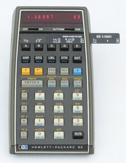
It was about August '73 when the new programmable HP-65 calculator was introduced. I just had to have one of those. It was awesome. Having that calculator helped broaden my math skills and, in addition, helped me better understand computer programming. What a fine instrument! I wrote several programs that helped me do a better job as a product designer. In general the programs were quite simple and recorded on little magnetic cards. As you recall the magnetic cards contained the program steps and to use the calculator one just inserted the card into the side of the HP-65, the card was read, and the program was ready to run. It was so slick.
Because most of the network group was moving to Santa Rosa I transferred to Brian Unter's section. With a tear in my eyes and mixed emotions I finished up my Network Analyzer preliminary designs and documentation and turned those papers and prototypes over to my replacement, Oleg Volhontsef. I said goodbye to Hugo and the good guys in Hugo's section then focused on many important, different and new microwave projects while working with Brian. As you recall Brian was my original boss when I joined microwave in 1969. During this period, Brian was promoted from a Project Leader to Section Manager.
Brian was a good guy, a good boss, a good friend and in many ways and I enjoyed working in his section. I knew I was a low man on the lab totem pole because all my co-workers were graduate engineers with at least a BS in EE or ME. Some had an MS or even PHD. Until that time, I never gave lab ranking, income, and pay curves much thought. One day Brian told me, "In a wage review the section managers agreed that I was underpaid for the work that I've been doing." So to enable some financial adjustments, they decided to rank me as having a BS degree in mechanical engineering based on the date when I joined HP. That opened the door for a higher position on the pay curve since the pay curve was referenced to years since first degree. As you know, I don't have a degree (but often wish that I did) nor have I ever attended any college. All the electronic theory I know is what I learned at the Spokane Trade School, in the Air Force, in my own shop, on the job, watching others or reading about technical things of interest. As a result of this ranking change, my pay continued to climb in bigger steps, more frequently and at a much steeper slope than when I worked in test, scopes or the early years in microwave. So I thank Brian and the other managers for making that income adjustment for me.
One of the first projects assigned to me by Brian was a means of testing attenuators. Many products at HP require Electronic Tools (ET) to aid in the production of a given electronic assembly or sub-assembly. The output attenuators in the 8640 and 8654 had a lot of components, cams and switches. They all had to be constructed correctly and the switches had to work in the proper sequence or the attenuator would be rejected. Because it's easier to test and repair the attenuator outside of the instrument, I designed and built a couple of test fixtures to test the performance of these devices. It was a short and fun project that actually worked better than I expected. It would quickly identify any problems within the device and defective parts could easily be replaced or proper adjustments made. All 8640A and 8654A attenuators were to be tested by this fixture before being installed in our new instruments.
In many of our new products we were using a unique HP assembly called a Rotary Pulse Generator (RPG). This component allowed the user to use a rotary knob to increase or decrease modulation, attenuation or frequency changes in our digitally controlled signal generators. Many users were accustomed to controlling signal generator parameters with a rotating knob rather than keying in a particular frequency, modulation or attenuation using pushbuttons. The problem is similar to telling time by reading a digital readout rather than viewing the hands on a clock. It takes time to mentally adjust to the new way of doing things. Actually, the digital readout and inputs are more precise but to this day, some folks still like to turn a knob to reduce the volume of a radio or rotate a knob to tune in the stations.
 |
New Rotary Pulse Generator |
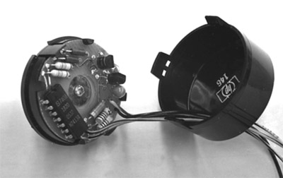
Our present RPG was quite costly to manufacture so Brian asked me to see what I could do to reduce cost. I worked with Russ Riley and Bill West on this project. Russ came up with a low-cost circuit design and I completed the product design. Bill helped with several production details. The RPG is a panel-mounted device that had a shaft with a knob on the front. As the knob was rotated, the RPG electrical circuit would cause an output of two square waves that were 90º apart. This phase shift in output would allow following circuits in the instrument to know if the knob is rotated clockwise or counter clockwise. When used on the front panels of our signal generators, If the knob was rotated clockwise the circuits would increase frequency, modulation or output level and CCW would cause a decrease in frequency, modulation or output level.
Inside the RPG we had a thin chemically milled fixed shutter and rotating shutter. The rotating shutter had slots appropriately placed around the outer perimeter of a thin flat disk. We had a fixed shutter with similar slots. We had a bulb projecting light on one side of the rotating shutter and two photo transistors mounted on the PC board on the other side of the fixed shutter. We had two set-screw adjustments to control the light reaching the photo transistors. As the knob was rotated the light reaching the photo transistors would be turned on and off at the proper time and sequence causing the circuit to produce the required pulses.
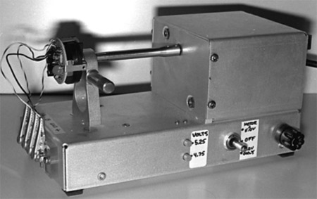 |
Motor driven RPG tester |
To assure that the new RPG was working as intended it was necessary to design and build a couple more electronic tools. This one was designed to provide power to the new RPG, to attach a motor to its shaft and rotate the shaft at a constant 100RPM speed. The outputs of the RPG were connected to the two vertical channels of an oscilloscope resulting in an easy to read display of output pulses amplitude, width, and timing.
Our final RPG design would snap together and was smaller, lower cost, adjustable, and was ultimately used in many of our microwave products and other HP instruments.
During the past year I've noticed an old dust covered 8640B prototype under Tom Grisell's workbench. It is serial number 1222A00056. It is one of our first lab prototypes. This 8640B was not in the best of shape because it went through Class-B environmental test. But it's been under his bench for over a year and it's not doing any good there so I asked Tom if it was surplus. It was! I asked Ray Shannon if I could have it since no one seemed to want it. Ray said OK so John Page signed a property pass and gave it to me. I cleaned it up, checked and calibrated it for proper operation of all circuits and have used it these many years. It still works like new.
Since I joined HP, I've actually never ventured out and solicited extra work for extra income. I don't know why, but frequently someone would ask me if I would be interested in doing some consulting for one company or another. Early '74 I got involved in helping to design a control panel for SHM Nuclear. I worked about 500 hours on their project. Our goal was to create a very large and sophisticated control panel and housing for a nuclear radiation device to treat cancerous tissue in humans. I spent a lot of spare time in my den and at SHM Nuclear understanding the need, checking component specs and making drawings. My shop and tools was invaluable for constructing a full scale control housing mockup of wood and plastic. The project went well, looked very professional and the additional income helped too.
Our daughter, JoDee, spent the summer of '74 working at HP testing diodes. This summer work is very helpful both from a financial standpoint and in setting a career direction for her. She is convinced she hates warehouse work and piece work. Testing diodes is driving her nuts. She can hardly wait for summer to pass so she can start Cal Poly in September.
Oh boy, HP came out with a new calculator. This time it's the HP-45. I've got to have one of those. I don't know how many more calculators HP will invent or how many more I'll be able to afford but it's got to stop soon. In the meantime, I'm having more fun with all these calculators. Some of my co-workers are teasing me about my calculator collection.
Then another consulting activity came along. He was years ahead of his time but later in the year I got involved with a company called "Resounding." Hal Baraclough, who once worked in HP Labs, was the boss, owner and inventor of a digital controlled FM Radio Receiver and Power Amplifier. His idea and the technology seemed impossible back in 1974 but most hi-fi of today is digitally controlled. There was nothing like it back then. His design called for a hand-held remote control to select the stations, adjust volume, balance, tone, etc. The main housing contained a very handsome tuner/amplifier with a panel bezel made of sculptured Walnut including a LED readout and a few enunciators. His project went well for a while and we were making good progress. He was anticipating sales in the hundreds and was investing lots of his own money selecting and buying parts to satisfy his future prototype and manufacturing needs.
Hal was a lovable guy and brilliant too. The product would have been a winner if only the funds held out. He had full scale models of the tuner and remote control but no actual working circuits that I'm aware of. I tried to get him to get the tuner and amplifier circuits laid out for PC boards and tested. I think he believed the first layout would work perfectly. In most new products, the circuit is designed, constructed and tested in parallel with the product design. The goal is to accommodate a working practical circuit.
I, along with several others, worked for him for a couple years. To accomplish his design he hired industrial designers, circuit designers, product designers and machinists part time. About then his wife got upset with him because he was spending all his free time and resources on this tuner/amplifier and remote control dream. She filed for divorce and he was forced to drop the project. I think they had one small child. I was involved in a legal battle between them regarding their assets and some deferred pay still owed to me. I was summoned to participate in a hearing with a judge and their lawyers. I have no idea how much money Hal spent total on the project. I've lost track of Hal and his project but often wonder about him and what is he doing now?
We had been making and selling the 8660B signal generator for several years. It had a couple of plug-ins that enabled appropriate modulation and output level selection. Because of some design changes and additional power requirements it was necessary to improve the cooling and heat-sinking of some of the power components so I was called upon to accomplish that task. To accomplish these modifications or production changes the Production Engineer normally would have taken care of them but due to his work overload, I was asked to pitch in and help.
 |
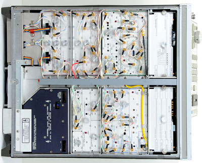
HP 11661, Part of the HP 8660B chassis assembly unfolds for servicing |
In addition there was an assembly in the 8660B that was a servicing nightmare. I was asked to make the necessary changes to this sub-assembly to make it more accessible and easier to service. This wasn't too difficult. The problem was simply solved by redesigning the supporting structure and including a piano-hinge along one edge of a rectangular sheet metal housing allowing the assembly to open like a book. When opened, all components, cables and connectors were easily accessible.
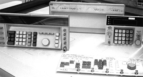
The 8672A&B family of synthesized signal generators included the 86720A Design, and the preliminary designs on the 86701B, 86710B, 86720B, 86721B. I'm having trouble remembering how all these products relate. These projects were not as memorable for me like so many others that I worked on. That may be because I was involved only part time on this product and never saw it to completion. I think some of the final product design was handed over to Charles Cook to complete. Some of the plug-in designs were done in Palo Alto and the mainframe design was done is Santa Rosa. These Frequency Synthesizers covered frequencies from 2.0-18.0 GHz. They were an amazingly successful product for HP.
I recall one small contribution that I made for the plug-in front panels. In addition to the RPGs, RF connectors, PC Slide switches, meter and frequency readout we needed a few push-button switches. In lab stock there was quite a choice of micro-switches. There was a little one about .30 wide, .45 long and .40 high. A single switch could mount on the front panel PC board. I designed a plastic molded key-cap just large enough to fit over the switch, that included ears to keep the key-cap from falling out of the rectangular panel hole. This resulted in a front panel mount, low-cost and dependable momentary push-button switch. We used that idea on several different plug-in front panels.
 |
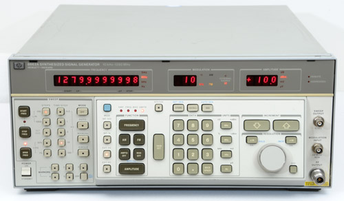
HP 8662A top view shows modular packaging |
While completing some of my earlier project responsibilities, I remember talking with Ham Chisholm about a new frequency synthesizer project that he was working on with Rolly Hassun. Rolly was the project leader on this project. He suggested that I get my foot in the door to become the product designer on this new 8661/2A. Ham was to design the digital control, frequency counter and readout circuitry. Ham told me that it would be a very sophisticated and interesting project and that Rolly was a fine project leader. I discussed it with both Brian and Rolly and they agreed that I should do the design. I had no idea what I was getting into but I couldn't have been happier.
Usually lab projects take one to two years to production. One sure thing I learned at the end of this project. . . it was a big one. We had twenty engineers working for five years on the 8662A. That's 100 man-years of top-quality engineering effort. It is a frequency controlled generator with an exceptionally low side band phase noise. The final product, the 8662A, contained 6393 total parts and assemblies. In the beginning I had no idea of the complexity, capability and reliability of this fine product. Helping on this project was another learning experience for me. I'll be the first to admit that every day, working in the lab at HP, I learned new things from everyone and anyone. What a great place to work and be paid for working there!
In the beginning there were just a few of us on the project and it wasn't clear to me what this unit did, how it did it, and who'd want to purchase it. About this time at HP there was a lot of focus on getting the product designer and production folks into new projects very early in its design cycle. I truly did get involved early in the 8662A design cycle.
When getting started on a new project I could list about a hundred different things a product designer needs to know. By now I had quite a lot of experience as a product designer. I realized in product design there are a lot of common elements from one design to another. It doesn't matter what the product is intended to be, there are just some fundamental things that I need to know. These questions are the same from project to project. Some examples are: project work order number, EEs and MEs on the project, what are their names, what are their responsibilities, what is the product, is there a block diagram available, what size cabinet do you want this to fit into, is there a schedule, are we on schedule, etc.
Well, to save some time I bring out this list of questions and give them to the project leader to answer. The all are important and make it easier to get involved in this new product. When I got started on the 8662A I gave the list to Rolly looking for answers. He answered about five of them, skipped over most of them and when he reached the questions, "Is there a schedule? He answered, "No." "Are we on schedule?" He answered, "Yes." It was our working relationship and his subtle humor that made working with and for Rolly just wonderful.
The final instrument size, shape, keyboard numeric entry system and readouts hadn't been determined but we were exploring all possible ideas. It didn't take too long to determine that in order to fit all the circuits in the box and all the buttons on the front panel we'd better settle on a System II frame size of 8.75" high X 16" deep. Five years later it was clear this was a good choice. The final product was dependably sound and densely packed yet ran cool. Its final weight was 65 pounds.
To this point I've mentioned the Clement "System I" cabinet design. The System I is based on the inch dimensioning system. The 8662 was designed into our new "System II" cabinet system. It is designed about the metric dimensioning system. About this time HP was converting from inches to millimeters and flat-head screws were 90º in metric rather than 82º in inch. So side frame tooling had to be changed for System II. And all hardware was mm rather than inch.
 |
HP 8662A Front Panel Mockups showing alternatives to project engineers |
I spent many early project days working on the front panel plan and how we might want to enter data and obtain readout information. I mocked up thumb-wheel switches with numeric readout, slide switches with numeric readout, rectangular key caps over micro-switches, etc. Many of our approaches had some merit but not right for this product.
We had the production experience of the older 8660B and its method of data entry including fairly large and expensive keycaps and switches. Even before the 8660B these same switches were designed into a desktop computer that HP made earlier. It was a temptation to use that keyboard design on the 8662A. In fact, we made an early mockup using those large keys and switches along with the rectangular key caps and micro-switches. It wasn't long until it was clear those keys and switches were too large, bulky and expensive for us to be able to fit in the total number of keys we needed in this product. So Ham and I worked with Bill West, a fine mechanical engineer, who developed the "West Switch."
 |
West Switch mounts on PC board |
This was a small simple dependable push-button switch that took about 1/4 th the room and cost much less. It was a simple, and clever design consisting of four parts. They were a housing, plunger, gold plated contact strip and tactile feedback stainless steel return spring. Included later was a key cap with the proper markings for the function desired. All the individual switch parts snapped together. A completed switch would be heat-staked to the front panel PC board for mounting.
I helped in the development by making a life-test device that would enable the environmental folks run a life test on several dozen switches for several million operations. We would then examine the switches for failures if there were any. This "West Switch" became very popular at HP and was used in many other products as well.
The "West Switch" cured the data entry problem. We decided on a mostly flat front panel with the data entry area tilted for ease of use. For the readout, we used numeric LEDs with a dot matrix pattern for readout flexibility and clarity.
But the true test of the West switch was when customers sat there inputting data into any instrument with that keyboard. Those nice large buttons clicked in with such a QUALITY feel, it was kind of like a ker-thuck, but they didn’t make a noticeable click. Their spacing was just right to prevent key interference, one factor that all HP product designers thought about, because stories had come back about Packard, in a product review, a big man, also had big fingers, and was known to complain about key spacing. . .
 |
HP 8662A became a world standard for low single sideband phase noise |
Early on, we decided we wanted a modular packaging system. It was clear there were a lot of independent interconnected blocks in our block diagram. In order to provide independent circuit design for each of the circuit designers it was prudent to come up with a flexible, well shielded but modular packaging scheme that would work for all. As you know, some circuits take more space than others. The packaging method has to accommodate small circuits as well as large ones but all had to be well shielded from one another and yet had to be within close proximity of each other.
 |
Extrusion compartments provide signal isolation between adjacent PC boards |
I wanted this instrument to be extremely serviceable from either top or bottom and utilizing a tilt-down front panel approach, components behind the panel could be easily accessed. I didn't want to have to remove modules to access buried additional modules. That just makes servicing a nightmare.
During the early stages of this project, I spent several months examining the shielding integrity of extrusions and identifying any potential RF sources of leakage between extrusions and covers and between extrusions and motherboards. In a sophisticated signal generator like the 8662A, we wanted no external signals from the instrument except the one that was intended to come out the front panel output connector.
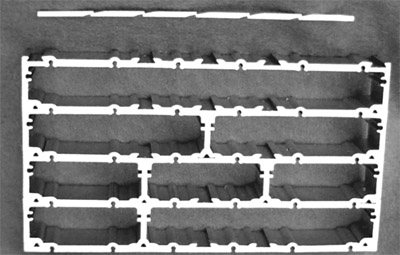 |
Interlocking extrusions offer great design flexibility |
It didn't take too long to focus on a family of interlocking extrusions rather than custom made housings or castings. We selected the extrusion family because they are quite low in cost and would allow us the flexibility to adjust the size of the shielded housing to accommodate any variation in circuit requirements as seen in the photo. The family of extrusions were full-width, 1/2 width, 1/3rd + 2/3rd width 3-1/3rd widths and end plate. We used element called a "shearing wedge" at each extrusion interface. Each pocket was well shielded from the other. There were locations for 14 screws on both top and bottom to secure the extrusion to the mother board and secure the covers to the extrusions. In addition to these screws we used copper waffled gaskets to seal any gaps between covers to extrusion and extrusion to motherboard.
The shearing wedge was a DeVries idea. It was a strip of aluminum that was to be inserted at the extrusion to extrusion sliding interface. After the extrusions were assembled and the wedges inserted, each wedge was pressed on both top and bottom. This caused the wedge to shear apart at the thin sections and wedge against the opposing extrusion surfaces. This insured a good electrical connection between extrusions resulting in good shielding between extrusion sections. Any slots or gaps between extrusions and/or other metal surfaces acted like a slot antenna and would radiate internal signals to the outside world.
The following story is a very unusual experience in my life but did expose me to an area of disease analysis and healing outside of the medical establishment.
In mid-October 1975, I answered my ringing telephone. It was Dave Baker, a friend that I had known for many years and who worked as a Materials Engineer for Hewlett Packard Co. He asked me if I would be interested in fixing an electronic device for Bev Ritchie, the manager at Eber Hi Fi in Menlo Park, California. Because I was very interested in Hi Fi, I said I would meet with Mr. Ritchie and learn more about this device to see if I could be of help. (I apologize if this gets a little technical. This could be a long story.)
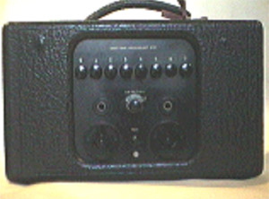 |
Oscilloclast, circa 1934 |
The next day I stopped in and Bev showed me this old (vintage 1934) electronic box called an Oscilloclast. This box had a knob and eight buttons on the front, and inside a couple transformers, capacitors, resistors, and two #27 vacuum tubes. The owner of this box was interested to know if this device was still working and wanted it fixed if it was inoperative. She suspected it to be inoperative but had no way of confirming it.
After I assured Bev that I was somewhat competent in electronic matters, he let me take the box (Oscilloclast) home to investigate it. I can't remember if I was given a schematic at that time but I spent some time tracing the circuit and checking what it was supposed to do. I learned that it had two oscillators. A Hartley oscillator working in the range of 43-44 MHz. And a low frequency oscillator in the region of 100 Hz/minute. I also learned that this RF oscillator was turned on and off at a 60 Hertz rate and that 60 Hz rate was turned on and off at a 100 Hz/min. rate.
I corrected the problems; poor solder joint, weak tube, and calibration. Since there was no convenient way to show Bev at his Hi-Fi store that it worked, I invited Bev to come over to my house to confirm that it worked correctly before I gave it back to him. To confirm that it worked used a HP 8640A signal generator connected to the "LO" (local oscillator) port of a mixer. The Oscilloclast output was connected to the "RF" (radio frequency) port and the "IF" (intermediate frequency) output was connected to an HP 130C oscilloscope. It was easy to see the zero beat of the oscillator and the frequency change with pulsing. He was pleased and impressed that it worked. I told him how much he owed me for the service and he took the Oscilloclast back to his shop and delivered it to his mysterious customer.
At this time Mrs. Packard (of 88 Faxon Road, Atherton CA) was keeping a low profile. Bev didn't tell me who his customer was until later. Bev and Mrs. Packard were members of the same church. Mrs. Packard is no relation to David Packard of the Hewlett-Packard Company.
A few days later I got a call from Bev asking if I had a few minutes to meet his customer to discuss the Oscilloclast repair. I said it would be convenient that afternoon after work. I met Bev at Eber's about 4:00 P.M. and he drove me to Mrs. Packard's home that was beautiful home at the end of Faxon road in Atherton. I liked her the instant I met her. She was very gracious woman, very pretty, hospitable, pleasant, and religious.
She was a widow of about 10 years when I met her. Her late husband, Gordon Packard, was a marketing manager at IBM She seemed well-to-do, living in a well kept, very nice home with beautiful surroundings and furnishings and a Japanese maid and gardener.
Mrs. Packard discussed the Oscilloclast that I repaired and gave me a little history regarding this device. She had some printed matter that gave me even more insight into the subject. That first meeting we spent a couple hours together and her question was: "Could I design and build a smaller, portable and modern day equivalent of her old Oscilloclast." The Oscilloclast was about a foot cube and weighed about 20 pounds. Mrs. Packard had about 6 or 8 different versions of the Oscilloclast that were built about 1938. Some were new and in the original carton. The original Oscilloclast or "Tic-Toc" was one of several inventions of Dr. Albert Abrams (Dec,1863-Jan,1924). The purpose of the Oscilloclast was to treat a patient to stimulate healing. Dr. Abrams had many physicians that leased his Oscilloclasts and hundreds of patients were treated by that device.
Another Abrams invention was the Radioscope which was used for diagnosis. This diagnosis and treatment, to date, has come about in several progressive steps.
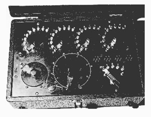 |
Radioscope |
First, Abrams found that when a cancer patient faced west, percussion revealed a dullness on the patient's abdomen.
Second, when a piece of cancer tissue was held close to the forehead of a healthy person, whom Abrams called the "reagent", percussion revealed the same dullness on the reagent's abdomen.
Third, the energy radiated from the cancerous tissue could be conducted over a wire to the reagent and produce the same dullness as when the tissue was held to the forehead of the reagent.
Fourth, by the same procedure not only cancer, but other diseases, could be detected by the energy radiated from the patient, or from a sample of the patient's blood.
It would seem obvious from Abrams' discoveries that disease could be identified by simply tuning in on the frequency that moved along the wire from the sample to the reagent's forehead. Strange as it may now seem, Abrams thought he was dealing with resistance. His first diagnosis device was made with rheostats which when set at 30 and 50 ohms, Abrams said he found the "vibration rates" of carcinoma because the dullness then occurred on the abdomen of the reagent. But identification of "vibrations" in terms of ohms of resistance on its face makes no electronic sense at all. And so it is not surprising that medical science at once branded Abrams as a fake without any investigation to see if perchance, the rheostats might have been inductively wound so that the settings of 30 and 50 could have fortuitously turned in on the frequency radiated by cancer. By that time electronic science had not developed enough to accept any such explanation of the Abrams' phenomenon.
A Canadian doctor, T. Proctor Hall, was curious enough to attend an Abrams seminar demonstration. Hall was so thoroughly convinced by what he saw that he read a paper before the British Columbia Academy of Science on April 27th 1923 in which he reported that Abrams' diagnosis and treatment really did work, although, "it seems ridiculously simple".
Mrs. Packard's interest and involvement in the diagnosis and treatment procedures came about by a series of progressive events.
Mrs. Packard's mother had malignant lumps removed from both her breasts. Then the malignancy spread and both breasts had to be removed. Her health failed to improve, and new symptoms appeared, so she went to the Abrams clinic. A blood test with Abrams' diagnosis device revealed a further malignant lesion, which had not been detected by other doctors during prior examinations. Abrams diagnosed it as terminal cancer but refused to accept her as a patient because her demise, which seemed imminent, would only add to the attack on Abrams by the American Medical Association. However, a chiropractor using Abrams' procedures accepted her as a patient and she was cured by the frequency treatment. Forty-six years later, when she died of a staph infection, autopsy revealed no cancer.
Next, When Mrs. Packard was quite young the family's doctors determined that she had tuberculosis, but they did not know how to treat her. However, a chiropractor in San Jose, California applied the Abrams frequency treatment and Mrs. Packard was healed.
A couple years before Dr. Abrams passed away in 1924 he founded the Electronic Medical Foundation in San Francisco. Dr. Thomas Colson was the one at the Foundation who developed and made practicable many of Abrams' procedures.
I later learned that Mrs. Packard's father, Fred Hart, had several patents on the Oscilloclast. Fred Hart was an entrepreneur in many activities. He had the first lettuce farm in Salines growing iceberg lettuce. He had the first radio station in this area in San Jose. His Call letters were KQW then later became KCBS.
In 1938, after selling his radio station, Fred Hart retired and offered his time and administrative talent to the Electronic Medical Foundation and the College of Electronic Medicine in San Francisco and became president of that foundation. Fred Hart added some new features to the Oscilloclast and got several additional patents on other devices. I have no idea how many Oscilloclasts Fred Hart made, sold or leased.
In 1953 The Foundation published a booklet entitled MOLECULAR RADIATIONS by Thomas Colson, B.S.,L.L.B.,D.O. and Editor, Journal of Electronic Medicine, 1928-1946. Fred Hart assisted in preparation of the booklet for publication. In the booklet Colson explained why the Abrams' procedure permits functions and diseases of the body to be discovered in the molecules (which are present in the blood) before the cells of the body are effected.
In the booklet Colson also reported on the development of the "Radioscope" which has a circuit designed after a radio receiver but which has no detector of its own but instead uses the reflexes on the abdomen of the reagent.
The Radioscope has a receptacle for a blood sample and its dial settings tunes in frequencies of the energy radiated from the blood sample. Each such disease frequency as it is tuned in is separately transmitted to the forehead of the reagent. And when the dullness occurs on the reagent's abdomen, it indicates the presence, in the blood sample, of the disease entity to which that particular frequency belongs.
The treatment for a disease is by application of a particular frequency in the 43 MHz range, which would cancel the dullness on the abdomen, which had identified its presence in the blood sample of that particular disease.
Over the years a large number of chiropractors and osteopaths made use of the diagnosis and treatment services of the Foundation until in 1953 the Food and Drug Administration (FDA) challenged the validity of the Abrams procedures and demanded an end to its activities.
Fred Hart said, "the whole treatment issue was that in the opinion of the Food and Drug Administration advisors, no radiation except radiation strong enough to produce heat, as in diathermy, has any value in the treatment of living tissue." In the course of the controversy, which lasted about ten years, Hart was sued; a consent decree was entered; and finally Hart was indicted for alleged violation of the decree. To avoid a costly legal battle, Hart entered a plea of nolo contendere and the Foundation was dissolved. Fred Hart had given to Mrs. Packard several Radioscopes and treatment equipment that included several Oscilloclasts.
The interesting thing is, Mrs. Packard believed that the Oscilloclast really did help to stimulate healing. She had been involved with it since she was quite young. She knew others that had used the Oscilloclast that cured problems that doctors had lost hope in curing. She had used the Oscilloclast often enough that she could tell if it was working or not. That's why she suspected that the one Bev gave me to repair was inoperative. I later learned that just by a treatment, Mrs. Packard can tell if the oscillator is on frequency and if the cables from the treatment oscillator are in good repair.
I considered her request (of building a transistorized equivalent) a couple days of thought and told her yes, I would design and build a smaller transistorized version of the Oscilloclast. I explained to her that I am a product designer, not a circuit designer.
In the begining I studied some literature that Mrs. Packard had given me on the Oscilloclast and experimented with a couple of her Oscilloclasts to learn more about the output waveform shape, frequency, modulation and level. I got circuit ideas for the transistor equivalent from books, studying schematics, and from transistor and Integrated Circuit catalogs. By December I had a breadboard of a working Transistorized Oscilloclast. We called it a "Pulsed Oscillator".
I continued building, testing, experimenting and communicating with Mrs. Packard for more than 25 years until she passed away. Summarizing these activities could take a hundred pages or more and is quite interesting but I won't include any more information about the Pulsed Oscillator project in these papers.
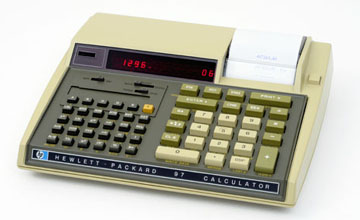 |
HP-97 Desktop Calculator |
In late October '76 HP came out with the new HP-97, programmable calculator. I was quite excited about that one. I just had to purchase one. It was like the HP-67 but with a paper tape for recording your calculations and calculator programs. It also had a card reader for the little magnetic program recordings. I'm happy that I got it and used it a lot for the next few years. Finally the card reader failed due to a rubber pinch-roller that turned into a sticky goo that coated the magnetic tapes and made the impossible to use. The recorder wouldn't read the tapes anymore due to the deteriorating pinch roller.
Because the HP 8662A was such a big and important project Rolly thought it would be good to give a presentation to all the folks that helped design, fabricate and assemble the parts for the "soon to be released" 8662A. Rolly asked me to put something together and present it to a couple hundred people in the HP conference room. I put together a slide show and demonstration that lasted a couple hours. There were two sessions, one on 11/14/77 and the other on 6/16/78. We displayed an assembled 8662A as well as all the individual fabricated parts set out on tables for examination. The attendees could see the many parts and how they fit together. Since many of the attendees were assembly folks and had little knowledge about electronics, I had 34 slides and presented a short lecture on DC, generators, AC, oscilloscopes, voltmeters, frequency, various types of modulation, output power, and frequency spectrums. I had three radio receivers around the room and would transmit from the signal generator to individual receivers set to a given frequency. The presentations went well and were quite fun.
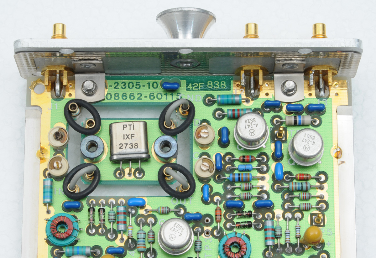 |
Vibration isolation for sensitive crystal filter |
There was always packaging challenges in the product design of the 8662A. One day Dieter Scherer came over and told me that in his circuits he had to include a couple crystal filters to eliminate some side-bands on the signal. These crystals are like very sharply tuned resonant circuits. The will allow only the passing of the frequency that is at the frequency of the crystal and all other frequencies are rejected. They are just perfect for this required task but they are very sensitive to vibration. You've probably heard of crystal microphones and crystal phonograph pickups. In those cases sound waves are converted to electrical voltages by the crystal. In our case the crystal filter would be disturbed by our fan vibrations and lab bench vibrations. Our fan was already mechanically balanced and mounted on rubber shock mounts to minimize conducted vibration. But we still needed to isolate our crystal filter. Dieter and I performed about twenty experiments using different techniques to isolate and shock mount the crystal. It was a memorable experience.
We mounted a small circuit (mother) board on the cone of a loudspeaker to use as a small shake table. I made up several daughter boards with various crystal mounting schemes. I mounted the daughter board on the small motherboard that was mounted on the loudspeaker cone. I placed an accelerometer on the daughter board to measure the amount of acceleration as the speaker was varied in frequency. We observed the output of the accelerometer on an audio spectrum analyzer. If the output observed on the spectrum analyzer was at a minimum or low, the isolation scheme was working well. The larger the signal the poorer the isolation scheme. Well after many measurements on many test boards we settled on using small "O" rings and posts to mount the crystal along with some mass to lower its resonant frequency. We connected it to the motherboard with some very highly flexible wire. This assembly gave excellent isolation in all of the three directions and we used it in a couple critical locations in our product.
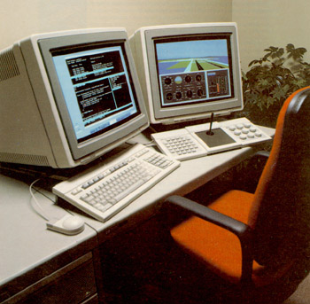 |
Computer Aided Design made Product Design so much more efficient |
We still didn't have computer aided design at the Microwave division at the beginning of this 8662A project. But, hang onto your hats. . . it won't be long now. Thanks to Jim Burnham for introducing me to a computer drawing system called "Draw." (Not to be confused with HP-Draw which came along later.) It was part of a computer circuit analysis program called "Spice." One day toward the middle of the 8662 project, Jim came over and told me about "Draw" and how it would allow the user to draw rectangles, circles, arcs, etc. using the computer. He showed me how to use it and I've been hooked on CAD systems ever since. I was the first one in the lab using it and was quite creative making various mechanical design drawings. Because of my interest in CAD, I was later asked to be the Microwave Division's CAD rep at various CAD meetings with other divisions.
A few months later Bruce Borrows came over from our HP division in Scotland and introduced us to a CAD system named "MINT". Folks at that division wrote the software for Mint. It worked on the computer System 1000 that we already had installed at Stanford Park. It was just what we needed. I immediately saw the benefits of Mint over the "Draw" system I was using. It didn't take long for me to use Mint for all my drawings.
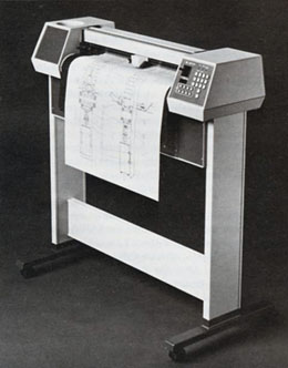 |
HP 7580A "Big Bertha" large format plotter |
In many microwave designs where transmission lines, strip lines or microstrips are required, before CAD we would make an image five or ten times size on mylar sheet and fill in the required area with red tape, photo reduce and etch the appropriate layers of a PC board. With MINT we would designate the shape and push the "Fill" button and the required area was filled with black. It cut down the design of the required image to about 1/20 the time of the old method. I used Mint extensively doing the design of Dieter's Oscillator described below.
Over a period of several months I trained all our product designers how to use Mint to make drawings. I spent several days in our Spokane Division training the designers in the use and advantages of Mint. For each of our designers we ordered and got computer terminals placed at their desks. From the computer all our drawings were then plotted on the HP 7585 "Big Bertha" Plotter. Our personal drawing boards were becoming just a place to set our computer-generated drawings. We could put away our electric erasers and pencil sharpeners. No more circle templates required. It was a new and wonderful era. I'm really glad that I could play an active part in our early CAD activities.
The subject of CAD could fill several pages but, about this time in HP history, several different CAD systems were available and being evaluated by various divisions. I'm sure I personally evaluated 6-9 different systems for our formal CAD system for our Microwave Division, and later, Stanford Park Division.
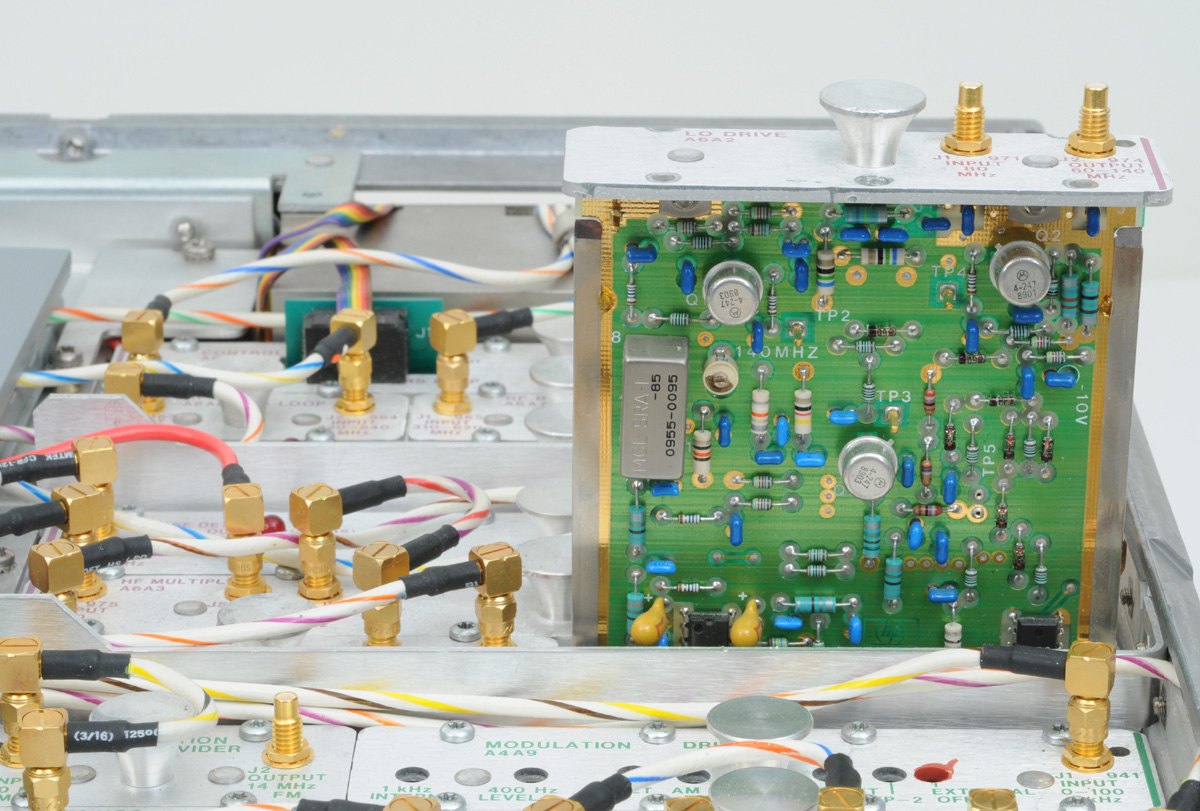
We always referred to them as Dieter's Oscillators. These were unique oscillators used in two places in the 8662A. They were constructed using copper clad thin Mylar sheets designed to be shorted transmission lines. The transmission lines were laid out on thin Mylar sheets using MINT our CAD system. These sheets were chemically milled then mounted surrounding a couple of Rexolite blocks. That assembly was clamped in an aluminum housing made of sheet metal and extrusions. The finished oscillators were mounted in a die casting, adjacent to the fan, and accessible from the rear in the 8662 along with the 10.0 MHz oven controlled reference oscillator. Because the crystal oven is intended to be warm we placed it away from the fan because the fan is used to cool components. By doing that we saved a considerable amount of precious power in this instrument.
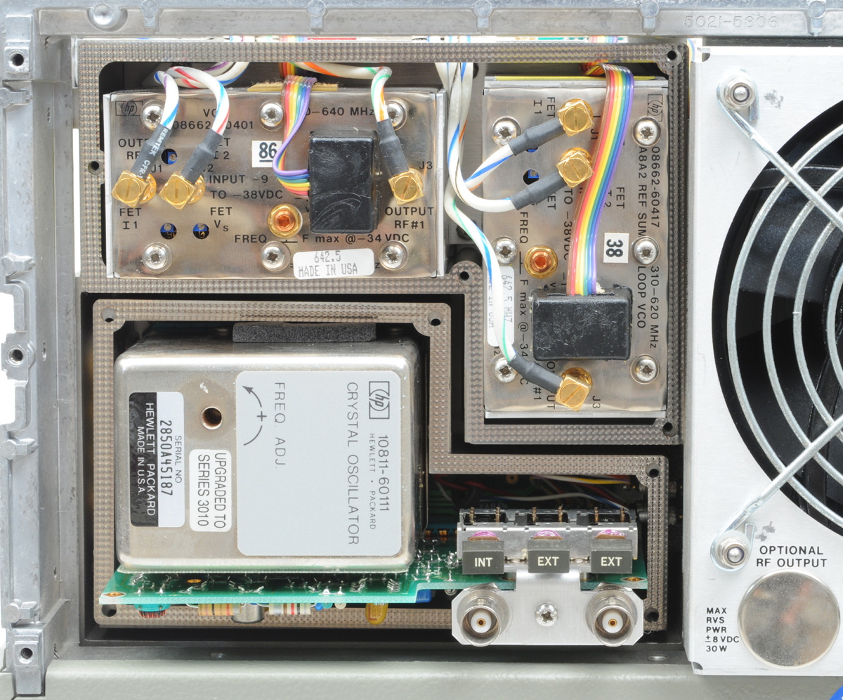 |
All three ultra-low SSB phase noise Oscillators |
It would take several pages and a smarter guy than I am to describe how Dieter's oscillators worked and how they were utilized in the operation of the 8662A. That really is beyond the intent of this chapter. I do know the oscillators were designed to operate in the range of 320 MHz to 640 MHz. I know that these oscillators along with the 10 MHz reference oscillator, 1/n loops, phase lock loops and some mixers and frequency doublers, we came up with a pretty fine frequency synthesizer that covered a range of 10.0 kHz to 1280 MHz with a resolution of 0.1 Hz.
It was my good fortune to work with more fine engineers i.e. Don Borowski, Bill Chan, Bill (Skip) Crilly, Fred Ives, Al Kovalick, Don Mathiesen, Dave Platt and John Richardson. These talented engineers, along with others working together over this five-year period came up with a major contribution in synthesizer design.
When I wrote the name, "Skip Crilly" above I was reminded of the dogged determination of the various engineers to make this the best product available. Skip did his part. I'm so impressed with him finding the solution to a difficult problem I want to tell you about it. The problem was intermittent spurs or side bands on the output signal. They shouldn't be there but were and could come from anywhere. Skip was determined to solve this intermittent problem. I couldn't tell you how much time he spent looking but by the process of elimination and careful analysis he found that the spurs were due to intermittent grounding of one of the shields of our triple-shielded coax interconnecting cables.
What is triple shielded cable? One could use just a wire and ground to connect the signal from one place to another. At these frequencies a single wire would radiate signals like an antenna. A layer of grounded braid around the signal wire would help. But that is not good enough. A layer of foil around the braid would help more. But that is not good enough. OK then another layer of braid around the foil would be even better. That works very well but our problem is that the foil was secured to a thin plastic film which was an insulator. The insulating surface was against the inner braid and would intermittently allow the outer foil to touch the inner braid. The solution to the problem was to wrap the signal conductor with the foil first with the insulating side against the center conductor. Then the two layers of braid were wrapped around the foil.
In the 8662A we probably use 30 of these special triple-shielded cables. In a critical location and under the right circumstances if the shield isn't solid and consistent it could insert slight changes on the signal. Because of Skip's fine detective work and thorough analysis we redesigned the triple-shielded cable so that the grounding is solid and consistent. Problem Solved. . . thanks to Skip. I loved working with guys like Skipper!
 |
HP 8662A Switching Power Supply |
One last, but important detail of this new product was the power supply. This design was completed by Gerry Ainsworth with the help of Al Kovalick and Marilyn Lawrence. His design was special in many ways. He developed a high frequency and efficient switching power supply design rather than a large 60 Hz power transformer, filters and regulators for the 650 Watts of power required for this instrument. His output voltages had very low ripple. The supplies were protected from over voltage, over current, shorting together, shorting to ground, and had a high temperature shutdown. All the various synthesizer circuits were protected as well as the supply.
It was my job to design this power supply circuit into the space available and assure everyone that it would dependably interconnect to the other circuit modules, conduct the voltages and currents as required and not radiate any unwanted frequencies from the switching circuits. It was mounted in a direct cool air path from the fan for maximum cooling. It was an efficient compact design. It was quite serviceable and primary power circuits were clearly marked for safety for the service technicians. It had some heavy components but they were mounted securely to survive our shock and shake tests. The 8662 is a very successful HP/Agilent product and is still in the HP catalog today (30 years later) selling for nearly $50,000.00 each.
After the 8662A was introduced and released to production I was asked to help develop the 8663A. As I recall, many of the components and specs were the same but because more circuitry was added we increased the length of the instrument three inches. This product was designed to have an extended frequency range, more output power and greater modulation capability. I worked on the 8663A for several months then it was transferred to the Spokane Division when several of my co-workers moved to the Spokane Division. The 8663A is a very successful HP/Agilent product and is still in the HP catalog today (29 years later) selling for as much as $70,000.00 each.
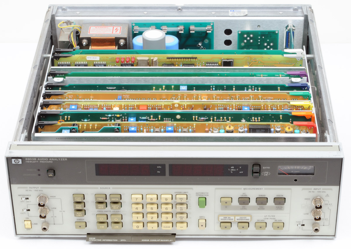 |
HP 8903A Audio Analyzer |
The last project of this section was the 8903A Audio Analyzer. I'm having trouble remembering the details of the project. I know that Jim Foote was the project leader and it seems to me that Derrek Kakuchi worked on the HPIB interface. I can't remember the others on the project. This project took only a few months of my involvement. A couple things I remember is that we wanted it to operate without the aid of a fan. By mounting the hot components on or near the outside of the rear panel we were able to run cool enough. The Front panel had a clean layout with logical locations for the "West Switch" pushbuttons. The most unusual detail is that the front panel BNC connectors were for differential input with a grounding switch for one of the inputs. We designed a single GR to BNC adapter so the user could use the GR (General Radio) connectors. We had those connectors on 3/4" centers to accommodate the GR connectors. The product was a clean simple design. It worked well, looked nice and we sold many.