HP Memories


This section might be a little easier to recall because I have some reference material that I've kept for these many years. I'll include some of my home and scope lab activities and learning experiences in the lab at HP. Because of the scope division move to Colorado Springs in mid '64, I left scopes on August 15, 1964 and joined the Magnetic Recording group. I'll write about that later.
On the home front, during '59 I spent a little more time moonlighting for Coopertronics. I was continuing to drill and mount components in his power supply chassis. I really wasn't tooled up to do a good job for Andy Cooper. I drilled the holes using either a hand drill or drill press and, if necessary, the holes were enlarged with various Greenlee punches. It helped the income a little though. Looking back, I believe a better use of my time would be to spend it with the wife and kiddies. As I re-read this, it looks like I spent all my time either at work or in my home shop, it really didn't work out that way. We did enjoy visiting Donna's folks at Santa Cruz and spending time on the beach and boardwalk. We visited my sister in Moraga, and went on trips and picnics to local or distant places. We even spent a few days at Disneyland when the kiddies got a little older.
A few times in 1960 I had to get after the lady who bought our previous Palo Alto home at 3417 Cowper. Once in a while she would pay the house payment with a check but had no money in the bank to cover it. I had to remind her in a few letters about paying on time and how banks and checking accounts work.
I better focus on my scope activities. I'll try to perk this up as best I can but reading about working in a lab can be pretty dull. It can be confusing unless the reader is really interested and pays close attention to some details.
The main area of confusion is calling my new repackaged scope a 120B for the cabinet model and 120BR for the rack mount version. For this summary let's call my redesigned 120A a "120BX." You'll see that later, we created another 120B oscilloscope packaged in the Clement "System One" instrument cabinet so, in the interest of clarity, we'll call the System One redesign of the 120A oscilloscope a "120B". Carl Clement was an industrial designer working at HP and came up with a completely new cabinet design. You'll see later where my 120 BX was redesigned into the Clement cabinet.
We certainly didn't waste any time getting started on a thorough examination of the new 120BX by everyone (it seemed). Even before I was assigned to the lab we started environmental tests on this new product. Actually at this early time in my career I didn't know there was such a thing as environmental tests and that department played such an important part in the development of a new product.
I'm sure you know this but environmental tests include several rigorous tests on a new product. The goal is to assure management and customers that the new product will work (hopefully within spec) under severe environmental (temperature and humidity) conditions. We want to be assured that the new product doesn't radiate unwanted frequencies or isn't compromised in its operation by unwanted and unknown frequencies. We also want to be assured that it will pass a reasonable shock, shake and package drop tests with no resulting damage to any components or chassis parts and will operate normally after these tests. These tests are like finals before graduation. It evaluates the designs and thoroughness of product and circuit designers and clearly reveals any weaknesses in the electrical and mechanical design and/or selected parts. I've often said, "Environmental tests separate the men from the boys." Later, as I designed new products I always had in the back of my mind, "How will this design survive in our environmental tests?
My oscilloscope activity covers a little less than five years. During those five years I was involved in several new scope designs. During my many years at HP as a product designer, it became clear that some projects took from one to five years to complete depending on the complexity of the product, the number of engineers on the design and changes made throughout the development cycle. Actually my 120B wasn't released to production until 10/26/61. (2.2 years after I entered the lab.) I soon learned that it was possible to juggle more than one project by carefully budgeting time and focusing on project "B" while there were parts being made in the shop for project "A." There were times later on when I was designing 3-4 products at one time. But in the beginning redesigning the 120A was a full time job for this amateur engineer.
 |
Designing before computers |
It surprised me, as a new kid in the lab, how poor my drawings were. I really hadn't done any mechanical drawing since my first semester of high school. That was 15 years earlier back in 1944. So my drawings were somewhere between poor to bad. No one fussed about them but this was my own assessment. The lettering wasn't consistent, the line weight was too light and wasn't uniform and the arrowheads looked just awful. I worked on them to clean them up and make the lettering uniform, readable and handsome. I've always admired well-done drawings.
At this time in the industry there was no such thing as computer aided design which came on the scene about 25 years later. Also all (or most all) of our fabrication drawings were dimensioned in fractions of an inch. Decimal dimensions and metric dimensions were not recommended at that time. Decimal dimensioning came a couple years later and millimeter (mm) dimensions came much later.
Dimensioning our drawings in inches and fractions of inches made fit and interface calculations a little difficult. Calculations were done using pencil and paper. A slide rule doesn't work for adding dimensions in fractions. We had no handheld calculators nor computers to use. They weren't invented yet. The accounting folks had adding machines but they were not available for us lowly product designers to use. Besides adding 1 1/2 + 3 23/32 on an adding machine would be of some help but awkward. (Actually, 1 1/2 + 3 23/32 = 5 7/32.) It wasn't until a couple years later, when we started using decimal inches, that I purchased an adding machine from Sears to help me with my design calculations.
(I'm digressing here. But, when HP went metric (about 1982), all drawings had to be dimensioned in millimeters. We included a chart on the drawing giving the mm dimension and its inch equivalent dimension in decimal inches. Since every mm dimension on the drawing had to show the inch equivalent it resulted in a big conversion chart as part of the drawing. In addition, the conversion chart took up precious space that could be devoted to drawing details. And creating the chart was a big job as some drawings had several hundred dimensions. As a result drawings ended up on larger sheets of paper.)
When Bill Bohnett and I worked on the 120BX in test, we had the help of Betty Downs to help create the tape masters for the PC Boards. Now that I'm in the lab it's my responsibility to clean up the PC boards, adjusting the spacing for proper component insertion and make sure the circuit is laid out correctly. In the beginning I did all my own board layouts. In general the PC Board tape masters are created two-times size and photo reduced to a 1:1 size. We generally used sheets of .010" thick Mylar. One sheet per PC board layer. Usually my boards were two layers, a circuit side and a component side. That infers two tape masters. We used special red plastic tape stuck to the Mylar for component pads and traces. Lots of errors can be made laying out PC Boards. One common error was connecting to a 7 or 9 pin tube socket and remembering if you are laying out the board looking at the circuit side of the board or component side. Many times when boards were fabricated and loaded the designer realized the tube had to mount on the wrong side of the board to work electrically due to layout errors. Boards got scrapped and a new corrected layout started. It amused me that the once head Printed Circuit Engineer laid out a PC board design and got the tubes in upside down and backwards. That proves the "Know-it-alls" don't actually know it all!
Later on and as time permitted I was called on to train various young ladies how to read a schematic and lay out PC boards. Some got very skilled at doing board layout and were an asset to product design and the lab. Later each lab had PC Departments that did that difficult and important task. Some of our more complicated instruments had 20 to 40 PC boards.
I was surprised how quickly many resources of HP focused on this new 120BX project and how much I had to learn. Looking back, I was treated as just another engineer and got wonderful cooperation everywhere I went. I was actually at an advantage because I had worked in production, knew lots of people and knew the location of different departments. Much to my surprise, many engineers stayed close to their lab bench and never ventured out of the lab. Everyone, both engineering and production, was very helpful. I was assigned a K&E 4-post drafting table, a tall stool to sit on and, I think initially, I shared a lab bench that contained space to store drawings and a working surface to build prototypes. I was back in the far corner of the lab, next to the back door, next to the windows and next to the library. I had a fine view of the hills looking up Page Mill Road in Palo Alto. My friend and sounding board, Eric Hammerquist, was just a work bench away.
I was weak on considering part costs. Initially, I gave part cost no thought at. When working on the 120A redesign in test, my goal was to just use the same parts but mount them differently. Actually my goal was to reduce assembly and test cost by the use of Etched Circuit Boards. The 120A was a very competitive product. We wanted to keep the costs low but still make a profit.
In developing a new product everyone gets into the act. The accounting folks got involved in a cost analysis. The production folks and production engineers passed my prototypes around offering constructive criticism for one thing or another to improve its appearance or ease of assembly. The marketing folks got involved by questioning the addition and/or deletion of various features. The material engineers got involved in component applications and sometimes suggested alternate, lower cost, components or even circuit changes. The tooling folks got involved in designing tooling for making chassis parts using steel-rule dies for cutting out the flat sheet-metal blanks and pad-form dies for folding the sheet metal. All these good suggestions (and some not-so-good) tended to complicate my day and many of those suggestions impacted the design. What have I gotten myself into, I wondered?
Even before I entered the lab we evaluated our first environmental test results. I joined the scope lab on September 15, 1959 but before that on August 21st I received back the results of the 120BRX environmental tests. It wasn't too bad but I didn't win any prizes. I remember during the shake test the vibrating heavy power transformer flexed the deck it was mounted on to such an extent that it caused a fracture in the metal deck. The fracture was from a sharp inside corner cutout for the transformer to the edge of the deck. During shake the operator looks for instrument resonances and shakes the instrument several minutes at resonance to see if there will be any failures. I was discussing this failure with Bill Myers who was the boss of Bill Thormahlen who was in charge of the environmental tests. Bill Myers suggested a radius corner in the transformer cutout to relieve stresses in that area. That was an excellent suggestion that worked over and over on other products I designed. Radius corners are good in both internal and external corners in sheet metal. They relieve stress concentrations and eliminate cuts and snags for the service folks. Every day I learned many new things.
We all know we like the external appearance of a product to be attractive to the customer. We had industrial designers hired to ensure good looking and human engineered products. I've always felt strongly about a handsome internal appearance of an electronic product. Being intimately familiar with military radar sets and other pricey equipment I gained an appreciation for neat wiring, laced cables clearly marked circuit boards and sub assemblies. It makes servicing the product so much easier. I wanted my 120BX to be clean open and easy to service. I received lots of compliments on the open clean design of the 120BX.
During this period the Tektronix Oscilloscopes were built as stated above. In addition to their easy-access cabinets and user-friendly front panels and well-designed circuitry, they had a handsome internal appearance, neat wiring, laced cables, clearly marked components and sub assemblies. They used their handsome white ceramic standoff component supports using silver solder to hold components in place. Their designs and workmanship was tough to match. But, fortunately for HP, at that time they had no low frequency oscilloscopes in their product line.
The 120BX design was modular and partitioned in a logical manner of several major sub assemblies consisting of: a Vertical Amplifier, Horizontal Amplifier, Sweep Circuit, Low Voltage Power Supply, and High Voltage Power Supply. Those along with the power transformer, Cathode Ray Tube (CRT) and chassis would result in a complete oscilloscope. The 120A was just one large chassis with all the circuits interconnected. It would have been difficult to sub-divide it into several sub assemblies.
This modular approach got our marketing folks quite excited about creating several other oscilloscope configurations to satisfy customer needs just by combining the right circuits and changing the size and shape of the instrument cabinet and CRT.
I was focusing on the 120BX and trying to complete the documentation including all part drawings, PC board tape master, material lists, test procedures, etc. I was working toward the completion of our pilot run of 5 ea 120BX and 5 ea 120BRX instruments. We built the pilot run and they went together well. There was a lot of enthusiasm and inertia regarding these new products. Some of the pilot run instruments went through environmental test again and passed without any great problems.
I soon realized there was a lot going on behind the scenes in other parts of the lab that would impact these products more than I ever dreamed. I worked diligently to take care of any environmental problems, correct any errors in documentation, and to be certain the tooling was coming along on schedule. I was ready to release the new instruments to production. But, much to my dismay, the whole project slowly came to a halt. I couldn't understand what was happening. Why were we holding on the release of the 120BX and 120BRX? In late January 1961, I wrote multi-page notes to important management folks like Ed Porter, Ralph Lee, Norm Schrock, Wally Klingman and others about the current status of documentation and tooling. We were ready to go! Why aren't we going? That answer is coming up later.
In our scope lab there were about 30 engineers working on other scope projects during this period. One major project was the 160A scope. It was militarized, big, heavy, and designed to have a much higher frequency response. It had a mainframe designed to accommodate separate vertical and horizontal plug-ins. During pauses in my 120BX activities I was asked to help product design some of the horizontal plug-ins for the 160A. I was happy to help. Being involved in other designs indicated that I'm more permanent in the lab and maybe they'll let me stay? Maybe they'll forget to send me back to test? I took on new projects with enthusiastic vigor and did the best I could to satisfy the project goals. I was really happy to be working in such a stimulating environment and with such great engineers.
The first plug-in project for the 160 Oscilloscope was the 166A Dummy Plug-in. This had no controls and basically filled the space if the user didn't need any of the other horizontal plug-ins offered. The next one was the 166B Time Mark Plug-in that provided intensity modulated markers on the scope trace so the user could measure frequency accurately. This plug-in provided several various microseconds between markers. The circuit designer was Scott McClendon. The next one was the166C Display Scanner Plug-in that allowed the user to plot the displayed waveform on an X-Y pen recorder. John Strathman was the circuit designer on this one. And the last one was the 166D Sweep Delay Plug-in. Floyd Siegel was the circuit designer. I think Floyd got a patent on this sweep delay idea and also on his beam finder idea. Sweep delay allowed the user to closely examine the horizontal scope trace and any portion of the trace expanded and magnified for thorough analysis. All these plug-ins had to be invented, created, designed, documented, tested, tested again and ultimately released to production.
While time was passing and plug-ins were being invented and designed there were four things happening that impacted my future product design activities. They were:
 |
HP 120H for Hughes Aircraft |
Marketing came back to the lab with some proposals and wondered if it was possible to create the scopes that follow. George Fredrick in our marketing department was most active in coming up with new scope proposals.
His first proposal was a scope we called the 120H Oscilloscope. This utilized a 3" cathode ray tube (rather than 5") and was in a custom designed cabinet. It was a standard rack width, 5" high panel by 11" deep housing. Hughes Aircraft wanted this 3" version for a test equipment system they were working on. It didn't take long to take the PC boards designed for the 120BX and find a way to position them in this smaller case with the 3" CRT. I got everything to fit in the box. It had an attractive and logical front panel layout. Cooling was accomplished by perforating both top and bottom covers and depending on convection cooling. It was a fun project that looked and worked well. We built two prototypes, one to show Hughes and the other to go through environmental.
Another scope proposal was a special scope for the U. S. Navy. They wanted a 120BRX equivalent only they wanted it less than 14" deep. They wanted a 7" high panel and standard rack width. I had no problem fitting the 120BRX PC boards in that cabinet size. Burt Squier and our CRT lab designed and made a special short 5" diameter CRT for this scope. Because the tube was shorter, the trace on the front could not fill the whole screen but the navy would accept that. I built a couple prototypes that worked well also. I sent one through environmental test. We soon learned the navy wanted it to withstand some military environmental specifications. We called this new scope the 120N. This project was turned over to John Tatum to complete. A year later he released it to production.
A third scope proposal was to make just an X - Y scope using two vertical amplifiers with no sweep circuits. This would use the same parts as the 120BRX but no sweep board and a vertical amplifier in place of the horizontal amplifier. Of course, the panel was changed to accommodate the different functions. This was easy to accomplish and another usage of the 120BX circuit boards. I think I built a couple of these but can't remember.
A fourth scope proposal was to make a special dual monitor scope for Sperry Gyroscope. They wanted a scope with two 3" CRTs and the appropriate circuits from the 120BRX to drive the CRTs. This project never got off the ground. It was really a special special. But these few paragraphs illustrate the interest and additional business the 120BX generated.
Our corporate industrial design folks (Carl Clement and Tom Lauhon) were creating a new modular cabinet packaging system for the HP company wide product line. This was a totally new cabinet design that was called "Clement Cabinet System" or later, "System One Cabinets." This cabinet system was about ready to be introduced. All they needed was an instrument to be designed into it. Also, the timing was such that the "Internal Graticule" CRT was about ready to be introduced. And, as you know, the 120BX is still waiting on the sidelines to be introduced. Our corporate folks thought it would be a good plan to introduce the new 120B with the new internal graticule CRT and in the new Clement Cabinet. That's a very good idea except the 120BX was not designed to fit in the Clement Cabinet.
I should digress here. What is an internal graticule, you might ask and who needs it? Using a calibrated oscilloscope one can measure voltage amplitude and frequency just by looking at both the trace on the oscilloscope screen and switch sensitivity settings. If you know how many centimeters or millimeters the trace is deflected and you know how many volts per division your range switch is set to, you can calculate volts of deflection. An example: the trace is deflected 3.0 cm. You are on the 10 Volts/cm range. Your signal voltage is 30 Volts peak to peak. In all earlier scopes, the centimeter scale was outside the tube face, etched or scribed on a piece of plastic in front of the CRT screen. There was always a parallax error in reading the trace amplitude. One had to be very careful taking data. The internal graticule was developed to be in the same plane as the phosphor of the CRT so there could be no reading error due to parallax. It was an ingenuous oscilloscope improvement.
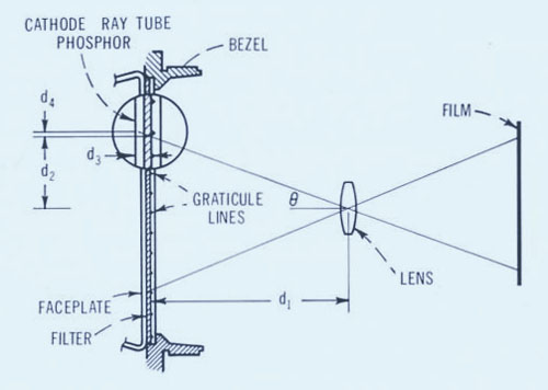 |
Diagram illustrating source of parallax error d4 in oscilloscopes. |
Several years earlier, I met Charlie Reis who was an engineer in the lab in building 8A. He was knowledgeable in chemistry, physics and electronics. He was a strange engineer always working on some new and wonderful invention or other. One of his major investigations was a method of electronically displaying numbers. I actually don't know of anything that he invented or designed that was significant or memorable. One day he came to me in the Scope lab and discussed silicon controlled rectifiers (SCR) that were quite new then. He talked about light dimmers and how they worked. He talked me into designing and building a light dimmer assembly for some project he was working on. I wasn't assigned to help Charlie but I just helped him get this hardware together for his project. In the meantime I learned more about SCRs and how they worked. I was able to integrate that work along with my oscilloscope design activities. In addition, and at a later date, Charlie had an idea about a digital clock that used Nixie tube readouts, neon bulbs for the colon and rotary PC switches for the numeric switching. An electric clock motor drove the four PC switches.
Nixie tubes were quite new then and were used in counters and voltmeters for a digital readout. Well this design was far more complicated and required some PC board layouts and hardware to hold it all together plus a case to put it into. I'm not really sure if this was a home project for Charlie or a work related project but we got it together and it worked quite well. Later he was after me to do more stuff for him but I turned him down since his requests had nothing to do with my assignments, goals and career. I was spending too much time on his projects and needed to focus more on the oscilloscope projects at hand. I don't know whatever happened to Charlie.
Guess who was assigned to repackage the 120BRX into the Clement Cabinet? Yes, it was about February 1961 when I started on the new 120B design. The 120B was the first HP instrument to use this new cabinet system. Dozens of various instruments followed later. This was a whole new ball game but an exciting challenge. Most mounting holes, front and rear panel sizes and shapes were pre-determined by the side castings in this new cabinet design. The product designer had the flexibility of determining how to use the interior space but the exterior was off limits for any changes! It was written that no product designers would dare make external changes on the Clement Cabinet system!
For an oscilloscope to fit in the Clement Cabinet, one critical problem had to be solved. The CRT was 16.75" long and the cabinet was only 16.00" deep. We had our CRT lab design a new internal graticule CRT that was about 15.75" long so it would fit within this shorter cabinet. For additional clearance it was necessary to put a small protrusion in the rear panel behind the CRT socket. The other problem was trace alignment with the internal graticule. It was necessary to create an adjustable magnetic field that would rotate the scope beam within the CRT so we could align it precisely with the internal graticule. This was accomplished by including a coil of wire around the CRT, after the deflection plates and inside the CRT shield. By causing a current to flow in the coil it created a magnetic field within the CRT that rotated the electron beam for precise alignment. That was an ingenious solution to an otherwise difficult mechanical problem.
In addition to these solutions we made some improvements in the 120A circuit design to allow the vertical amplifier to display a wider bandwidth and to enable the power supply to operate at lower power. We reduced the power dissipated by the DC Filament supply by using a 12V zener diode and series transistor regulator rather than a vacuum tube regulator. We added a Beam Finder, Sweep Expand switch and Trigger Level to the front panel controls.
There continued to be a lot of discussion about the Clement Cabinets over the years. Clement and his styling team insisted there will be no holes in the top nor side covers in his new cabinet design. I agree, the cabinets looked nicer without ventilation holes to enhance cooling. But it wasn't the real world. The cabinets were designed as a thermos bottle with a bright aluminum interior and a vinyl covered exterior. As a result, the temperature would rise to a maximum because there was no place for the hot air to go. We considered a fan in the 120B but there was no room for it. We compromised and the final instrument had a solid top cover, perforated bottom and side covers. We also had vent holes in the rear panel.
Our goal was to have clean prototypes ready by August '61 so this product could be introduced at Wescon (Western Electronics Conference), a very important trade show. With some design help from Barney Oliver and Carl Nale we were able to reduce wasted power that lowered the temperature rise of the instrument even further. We passed our environmental tests and we achieved all our goals.
In July/August '61 there was an HP Journal article devoted to the new 120B, internal graticule CRT and the new Clement cabinet. In October '61 this product was released to pilot run of 10 instruments. Then to production for first delivery scheduled for 1/15/62. The 120B was slow in coming but well worth the wait and was a sales success.
About this time, HP was breaking up into several different divisions. We had the Scope Division, F&T (Frequency & Time), Microwave and Audio division. The Scope Division moved back down to Building 7 at 275 Page Mill Road. Several more scopes were designed into the Clement cabinet. I got involved in a couple of them. In addition I was asked to help with some design details for the 175A and 185A Sampling Scope.
I can remember like it was yesterday working with John Strathman on the 130C. John was a fine circuit design engineer. We had mutual respect for each other and got along well. There was another fellow assigned to design the Power Supply design for the 130C but I can't remember his name. The HP 130C design was a hybrid. It utilized both vacuum tubes and transistors. More and more we were seeing transistors appear in some circuits in all our HP products. This project progressed well and was working well.
We were passing tests and reviews one after another. We were getting close to a pilot run release when one evening, long after quitting time, John was working late on his prototype 130C. He had this serious and worried look on his face. One could easily tell when John was upset.
 |
The HP 130C |
I asked what was bothering him. He told me that his 130C amplifier was oscillating and he just couldn't figure out the reason for it. (An oscillator is really an amplifier with positive feedback that causes it to oscillate.) John's amplifier had lots of gain, and covered the band from DC to 600 kHz. He had been working on this problem for a couple days. He said he had tried everything to get it to stop. I asked him to show me how he knew it was oscillating. Now, I'm not a circuit designer but I know a little about circuits and interpreting oscilloscope displays. So John showed me the problem. I sat and looked at it for a couple minutes. I adjusted the sweep time switch and trigger level setting and said to John, "John, here is the solution to your problem, your amplifier is not oscillating, it is picking up KGO the local radio station." It was clear to me, and true too, that the high frequency that we were seeing was being amplitude modulated and if John put a speaker in place of the CRT, he could be listing to music or news of the day.
I went to lab stock, got a coil and variable capacitor and made a tuned circuit, hooked an antenna to it, plugged it into the vertical input of his scope and we tuned in a very large signal of this same radio station. John was so relieved. His problem was solved. He had no oscillation nor amplifier problem. The amplifier was very sensitive and just picking up local signals. It was doing what it was designed to do.
This 130C project continued forward with ease, it passed all our tests and reviews and was well received by our customers. I still have a working one on my bench here at home. It's 41 years old and still works and looks like new.
 |
HP 132A |
My next and last scope project is the 132A. Sometime after getting started on this project the company decided to move the scope division to Colorado Springs. Oh my, no more scopes in Palo Alto. What should we do? I really loved all the scope projects and the folks I worked with. I couldn't have been happier working with scopes. HP offered to send many scope supervisors, engineers and spouses to Colorado Springs to see if they would want to stay with the division, move there and continue designing scopes for HP. So in May '64 Donna and I got a flight to Colorado Springs and spent a week looking at the new plant, homes and environment. Not a bad place to live but Palo Alto isn't too bad either. After much anguish and soul searching we decided not to move. We just had too many good reasons to stay in Palo Alto. The kiddies were in school by now, Donna's folks lived nearby, we had a nice home and lived close to work
I continued designing the 132A. This scope was unique in that it had a CRT with two electron guns. It was exactly like two 130C scopes in one box but with only one display. Since I was intimately familiar with the 130C I was asked to make the few circuit design changes as well as complete the product design for this dual beam project. Later, Dick Monnier was asked to be the project leader, to create a block diagram of the 132, design a couple amplifiers, monitor progress and make suggestions. We had a couple summer students help us too. One was a Stanford student, Roger Williams and an exchange student from Berlin Germany, Eckhard Kienscherf. They all helped a lot getting this product together and keeping it moving.
It's interesting to note that when I was test line leader, Dick Monnier was a new engineer in the lab. HP had a rotation program for new engineers and many of them worked for a week or two each in the shops, assembly and test. Dick was an excellent test technician for the few days he worked on my line. He worked the turn-on position for the 130A and I remember him to this day focusing on a stubborn inoperative power supply problem. He finally found the problem and fixed it.
 |
A two tube sandwich package |
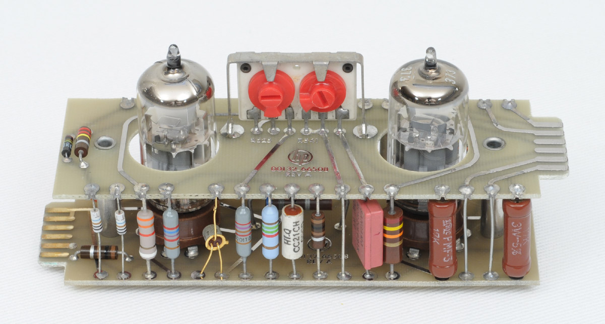
The 132A was designed using a unique packaging scheme that came to mind one day. It was so unique that Packard came to see it and said, "This is the best idea I've seen come out of this lab in years." It also was featured in a publication called Electrical Design News. It got a lot of press in HP publications. It was called "Cordwood" or "Sandwich Circuit Packaging."
The package is made up of two PC boards parallel to each other and spaced about one inch apart. Both boards have traces on both surfaces. The lower board accepts and supports the tube sockets. The upper board has cutouts for the tubes to protrude through. All the required components of the circuit are mounted between the lower and upper boards. The advantages of all of this is good utilization of instrument volume, good air flow between components, good isolation of troublesome components, ease of trouble shooting of circuits, and ease of mounting this modular circuit assembly.
The 132A used this packaging technique on its various assemblies. They all plugged into a large mother board spanning the instrument from side to side and top to bottom. There was very little wiring required because the mother board did most of the interconnecting. The instrument was convection cooled. Air came in the perforated bottom cover and exited through a rear perforated top cover. (Sorry, Mr. Clement.)
As long as vacuum tubes were used in our products, this new packaging idea made sense. But my timing was such that tubes were on their way out. Future scopes were mostly all transistor. The 132A was the only scope that used "Sandwich" PC boards.
One weekend I just had a lot at work to accomplish. On Friday evening I discussed it with Donna. We had several things planned for the weekend and I didn't want to disappoint Donna nor the kiddies. I suggested that on Sunday morning I would get up really early, about 2:30 AM and go to the lab and work till about 7:00AM and come home and have breakfast and a normal Sunday. She agreed that could work OK.
It was a lovely warm summer night. Not much traffic at that time of the morning. At about 2:45AM I entered the front lobby of HP at 275 Page Mill Road. Both front doors were wide open. Much to my surprise both security guards were fast asleep on the lobby furniture. Several thoughts entered my mind. Who is guarding these premises? Should I sign in without waking these sleepyheads? Should I call Ed Porter and report them? Should I wake them and sign in? Maybe I should go back home and let them sleep. I made a little noise and one of the guys woke up and stomped his feet and walked around the lobby trying to get his head together. He scolded me for coming to work at this ungodly hour. I took his scolding like a man but didn't want to argue with him. I signed in, did my work and went home about 7:00AM.
On Monday I told my dear friend Mary Elledge about my security guard experience who told her hubby, Keith. Keith worked in the front office. To make a long story short, the guards(?) were relieved of their HP duties. I've often wondered how many other nights have these folks snoozed on the job? It is certain that some security guards are better than others are. I could tell more security guard stories, but not now.
This 132A project went well through all the tests and evaluations. We built several prototypes here in Palo Alto. The pilot run and production runs were to be built in Colorado Springs. On 8/6/64 I went to Colorado Springs for a week to teach a class on the 132A design and transfer the design, documentation and wiring samples to Dave Davidson.
I was asked by marketing to take the 132A to the Machine Design show in New York City. I had booth duty each day and demonstrated the operation of both the 132A and a multi-channel strip-chart paper recorder we called the "Bandsaw" recorder. This Bandsaw recorder got lots of attention, especially by the Brush Company representatives. The Brush Company made several different models of paper recorders and wanted to see and study the competition. It turns out that our Bandsaw recorder never got very far off the ground. That project was discontinued after the pilot run of ten instruments and after the show. But, the 132A became a success. This New York trip was memorable in many ways but convinced me that I wouldn't want to be in marketing as a career.
This was my first trip to New York and I wanted to see as much of it as I could during the few days of the show. Every spare minute I would either be walking by myself or with other HP folks up and down the streets of New York. You really can't get the feel of a new city by riding in a taxi, bus or subway so everywhere I went, I walked. I was standing at booth duty every day. Also at night we wandered up and down the streets and enjoyed the sights. More than once were propositioned by ladies of the night, but turned them down. Sipping a short one in a bar a lady came over and made some interesting proposals. . . sorry lady.
Anyhow, the point of this paragraph is not the ladies of the night but I was on my feet so much and in uncomfortable tight fitting dress shoes by the fifth day, I just couldn't stand. I'll never forget that last morning in my hotel room. I jumped out of bed, landed on my feet and my ankles gave way. I couldn't stand. That never happened before or since. Holy-cow, what'll I do now? I couldn't stand! I had to stand. I had to get dressed and get to the last day of the show and get on a plane and go home. I couldn't stand! I really didn't know what to do. I was too embarrassed to tell anyone or call for help. I sat on the edge of the bed thinking about it. I've got to stand! I've got to get dressed and walk out of here! I somehow got it all together and accomplished that task. Maybe just moving the ankles a little and rubbing them fixed the problem. I'll admit that I didn't walk very fast for the first couple blocks but later I was OK. Maybe it was the combination of tight fitting, leather dress shoes on hard concrete for several days in a row that caused the problem. Give me the comfort of casual dress product design, sitting on my duffer any day over the dressy discomfort of a tie-wearing marketing guy.
As time passed and HP was growing we developed more tools and aids for both the circuit designers and product designers. Two of my favorite aids to excellent and consistent engineering that come to mind are the "HP Manufacturing Engineering Manual" and the "HP Preferred Parts Manual." Both of these books were invaluable as we developed new products. The Manufacturing Engineering Manual was most useful as an aid to practical mechanical engineering practices at HP. It provided engineering information such as: standard hole sizes, standard fold radius for sheet metal, standard casting practices, standards for plastic molding practices and later standards for extrusions and semi-rigid coax fabrication. (I wrote the sections on semi-rigid coax and extrusion later in my career. The preferred parts manual was precious in that it provided part numbers and descriptions of corporate approved parts to use in our new designs. The parts were preferred because they did the job well and were lower in cost due to large purchases. Later, about 1985 we had "Colossus" on the computer. That program listed nearly all purchased parts that HP had and was a convenient method of finding the part number of most any item you might need for a new design. It used cross indexing so you could enter the database with part's specs.
That's pretty much what I did in the Scope Lab at HP. They never did send me back to test. In fact, the scope folks gave me seven raises during these past five years. So I think I'll be in the lab for good. It's pretty wonderful being paid for doing something you really enjoy. After these few short years in Scopes, and the group moved to Colorado Springs, I was really fortunate to be permitted to join Walt Selsted's Magnetic Recording Group. My design experiences and contributions in Walt's tape group continued on for another five years.