HP Memories


I left scopes on August 15, 1964 and joined the Magnetic Recording group. The time spent in Magnetic Recording was about 4.5 years.
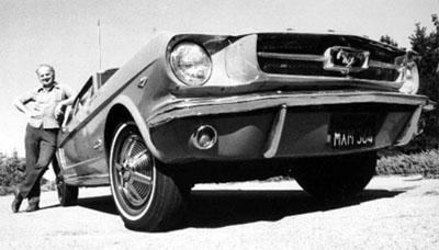 |
My Pepper Red Mustang |
Meantime, before I get in too deep telling you about my magnetic recording activities, I must tell you that this year, 1964, is the year Ford came out with the original Mustang automobile. The only car I ever really fell in love with at first sight was the Mustang. I had to have one. I loved the sporty look, body style and color choices. My first choice was a bright red convertible. We didn't really need another car, and the Mustang was a little small for a family of four but it was so beautiful and hot. Fortunately for me, Donna's dad loved cars. On Father's day her folks were visiting us from Santa Cruz and Fred suggested the two of us go to the Ford store in San Jose and see if they had any new Mustangs.
Mustangs were just introduced a month earlier and selling so fast there were very few available in the bay area. Fortunately for us they had one on the floor. A bright pepper red hard top. It was actually used for about a week, purchased in Detroit and driven out here so had about 3000 miles on it. It was for sale as new and had a new guarantee. It was my dream to own this car. Good ol' Fred pulled out his check book and we bought it on the spot. I paid him back later but that was a memorable day for me. Donna and I enjoyed it for many years and later gave it to daughter JoDee when she entered college. She is still using it to this day. She had it repainted and engine replaced but 42 years later it still looks and runs like new. My friend, Larry Johnson, took the above photograph.
As we go through life there is sometimes a "Y" in the road. We are forced to take one branch or the other. You just can't stop and wait at the junction of the "Y", you must continue forward. I've often thought, what if I took a different branch? In general I've been very happy with the career choices I've made. This next branch in the "Y" was rewarding in more ways than one. Meeting, knowing and working with Walt Selsted has been a big part of my life. If I took a different path. . . who knows what life would bring?
This may be a long introduction to our dear friend, Walter Selsted. I would guess it was about May-June of '64 that I attended a scope lab lunch and meeting. The guest speaker was new to me and a fairly new guy hired by Bill Hewlett. Walt was a nerdy looking guy. When Walt joined HP, he was initially assigned to Advanced Research and Development and he reported to Barney Oliver. Before coming to HP, Walt was head of Ampex R&D. Ampex was founded and started developing tape recorders right after WW-2 and Walt was one of their first employees. He made technical contributions to many recorder developments as well as their development of the rotating head video recorder. He had been awarded many patents. Walt was a Vice President of Ampex Instrumentation Recording Division when he left. He left Ampex to help HP develop a multi-channel instrumentation tape recorder. Our eastern medical division (Sanborn), needed these recorders as part of their patient monitoring systems. Walt Selsted and Bill Girdner, an old-timer HP Mechanical Engineer, developed a new 10" reel-to-reel instrumentation recorder for Sanborn. Walt was going to tell us about its design and why they designed it the way they did.
Walt's talk was interesting and memorable in many ways. His approach was to give an electrical analogy to mechanical functions. He was knowledgeable in both electrical circuits and mechanical devices. He was just brilliant and his lecture was captivating.
Our Microwave Division had all the fine CNC mills and lathes that money could buy. Those tools were used to machine castings, housings and turned parts for our microwave assemblies. It just made sense to locate Magnetic Recording in the Microwave Division. The large cast aluminum housings for the tape transports used in our Instrumentation Magnetic Recording devices and other machined parts required sophisticated and capable machine tools. It wasn't long until management made Walt's group part of our Microwave Division. When that occurred, Walter reported to John Young the Microwave Division Manager.
Because scopes were moving to Colorado Springs, and after much pondering, Donna and I decided to stay in Palo Alto so I had to find someone who would have me. The next most interesting place that I would like to work would be in the tape group. I was very interested in audio tape recording and I know I'd learn a lot by working in that group and for a brilliant guy like Walt.
From when I was a little boy I've been interested in audio recording from cutting phonograph records and later, recording on wire and tape. My brother, Adrian, demonstrated a wire recorder to me back in 1946 when he worked at KFPY, a radio station in Spokane Washington. I couldn't believe what I was seeing. How do you record sound on a very small wire or thin length of plastic tape, I wondered? It makes no sense and seemed like black magic. I had to learn more about that. There was no training in wire or tape recorder theory at my trade school. We were studying Ohm's law and simple circuits most of the time. There was no training about tape recording in the Air Force. Their training was mostly about radio communication and radar navigation and bombing. And while on the road for my dad, I learned nothing about tape recorders. With that background, it makes you wonder why they would even let me near our new magnetic recording group.
Starting about June '64 every time I had a chance I'd walk by Bill Girdner's desk and chat with Bill about working in their small recording group consisting of Bill and Walt. (It was a very small group. If it had one less person it wouldn't be a group at all.) I didn't know Walt at the time. He seemed too busy and consumed with his important tape transport design to be interrupted by me seeking my next job. Walt has lots of nervous energy and seems always on the go and even a little impatient. After working with him I learned that he was never too busy to explain or help analyze a technical problem or crack a joke. He was a hands-on manager. He has a fun sense of humor. But, not knowing him, I didn't want to bug him so I picked on Bill. At the time I had no idea what their plans for the future were. Fortunately for me they did have future plans. HP was just getting into the tape transport business and had plans for more and better instrumentation tape recorders and systems. To help move that plan forward, Walt soon hired a fine circuit designer, Jerry Ainsworth.
One day I was chatting with Bill Girdner when Walt came over and said, "Bill tells me you would like to be part of our group. Very soon we will be working on a wide-band tape system and we need some good product design help." He then introduced me to Jerry. He told me, "If Jerry gives the OK, you would be welcome to join our group." My interview with Jerry went well so, as soon as I finished my scope obligations, I would be part of Magnetic Recording.
One thing I learned and admired about Jerry is that he is one of few circuit designers that did the complete design of his circuits on paper including detailed operation and circuit compensation at high and low temperatures. Then he created a complete and detailed schematic. Then he and I designed and built a prototype of the circuit to confirm that it worked as intended. Jerry's prototypes always worked perfectly. (Jerry later had the aid of a fine technician, Wally Overton, to take data, make measurements and check system performance.) Many circuit designers design by trial and error. They make prototype after prototype and still don't get it right. Jerry knew what he was doing and did it well. Another fine engineer, Russ Riley, designed the same way. Fortunately for me I was able to product design for both Jerry and Russ during my HP career.
As a product designer, working elbow to elbow with various circuit designers, we get calibrated quite quickly on the circuit designer's skill level. A good measure might be the number of PC board iterations one must go through to a final design. Or product design changes required because of missing features or capabilities. Many folks get into the act and influence the final product but working with various engineers, I've learned that some are better than others. Some really have their act together. . . some don't even have an act.
As time went on, Walt's tape group expanded and we later merged with a small Digital Tape Instrumentation Company HP purchased called Datamec located in Mountain View, just south of Palo Alto, which became the Mountain View division. I'll discuss the Microwave Division tape projects first, then a product I helped developed at Mountain View Division.
One lovable thing about Walt is that he was very personable. At coffee breaks, morning and afternoon, our group of guys would gather at the coffee table and discuss various issues of the day. One day the subject was quite technical and Walt was explaining how a circuit worked. He needed to draw a picture on some scratch paper but there was none available right there and then. Rather than leave the coffee stand and get some paper, Walt picked up a sugar cube from the box provided and with a ball-point pen drew the schematic on the lump of sugar. That brought a lot of laughs and conveyed his technical message. Walt was always a very quick thinker, innovator and I later learned he could immediately find the weaknesses in any electrical or mechanical design.
We had one memorable engineer who was loud, somewhat obnoxious and not too much fun to be around. He usually came later to coffee breaks but would always elbow his way through the crowd so he could stand face to face with Walt. Now, Walt could notice and be impressed by him. Were we jealous? Were we offended? No, I think we were more amused than anything. Were we annoyed? Yes! He was so obvious. It takes all kinds of people to make up a lab. He was a good electrical engineer but not the best I've seen and his personality needed some work.
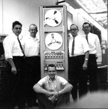 |
This photo (L-R) shows Girdner, DeVries, Overton, |
Describing my tape system activities gets a little complicated. I'll try to keep it simple. While at the Microwave Division we developed two major tape systems. Our first system was a high frequency (1.5MHz) system called a 3950 Series. The second one was a low frequency (300kHz) system called a 3955 Series. These were large systems mounted in cabinets seven feet high by a couple feet wide and deep. A typical system was made up of tape decks that could accommodate either 1/2" or 1.0" wide tape. Tape 1/2" wide enables a record/reproduce capability of 7 channels and 1.0" wide tape has the capability 14 Channels. We could accommodate reels of tape either 10" or 14" diameter.
The systems included a special housing mounted in the transport for pre-amplifiers and below the transport we had cabinet/s for plug-in record and reproduce electronics. These electronics could either be FM Record and Reproduce and Direct Record and Reproduce as required. Even these Record and Reproduce electronics had little equalizer plug-ins that were designed to match the selected tape recorder speed. The transports could run at 1.75, 3.5, 7.0, 15.0, 30.0, 60.0, and 120.0 inches per second tape speed. We had equalizers for each speed and for each channel. The system was designed to be very versatile, interchangeable and custom built to satisfy the customer's needs. Our pilot run of the 3950 system included 13 each record and reproduce mainframes, 88 each record and reproduce plug-ins and bunches of equalizers. I don't know how many transports but would guess 13 also.
An impressive example of the 1.5 MHz system is that at a tape speed of 120"/Sec the bandwidth of the system was flat from 400 Hz to 1.5MHz. That means that the entire AM broadcast band could be recorded all at one time on each of seven or fourteen tracks. The AM broadcast band could be recorded by connecting an antenna to the input connector of Channel One. To later listen to it in playback one could use an AM radio connected to the output of Channel one and just tune to the AM station of choice. That experiment only used the bandwidth from 500kHz to 1.5MHz of that channel. The band below 500kHz could be used for something else. That experiment uses only one channel of the seven or fourteen channels available. These systems could record and store a lot of data.
On any new product, we product designers work very closely with the corporate industrial design department. As you know, the industrial design folks consider front panel human engineering, customer interface, ease of use, panel colors, knob sizes, logical panel layouts, etc. Their proposals greatly effect what occurs behind the panel. Sometimes their ideas and proposals aren't practical or the interior design is affected by the front panel layout. So, it's really necessary for us product designers to work closely together with the Industrial Designer and either of us can effect the project schedule if we drag our feet on an issue.
The industrial designer assigned to the tape system project was Tom Lauhon. I've worked with him on other projects before and after. We had a good working relationship. He was a fine and skilled industrial designer. But, he drove Walt nuts. He spent nearly a year selecting a general design and colors for the tape systems. Walt was frustrated because Tom was becoming the critical path and parts couldn't be designed, tooled and ordered until he settled on the color scheme and design that made good sense. Walt's frustration level was so high that he went to Young, Barney, and finally Packard to get some firm decisions out of the industrial design department.
They finally came up with a handsome system and we were able to move forward. Lead-time can be quite long when designing and ordering parts for new products. We didn't want the industrial design folks to delay our introduction unnecessarily. Production tooling can be a serious lead-time problem getting tools designed and fabricated to make extruded, cast or plastic molded parts. The product design or part design process has several steps. Each step takes a certain amount of time.
The steps for developing a new part might be:
This new tape system design utilized sand castings, die cast parts, plastic molded parts and extrusions. By this time I was quite knowledgeable about sheet-metal design but the other fabrication technologies were foreign to me. All my previous designs utilized sheet metal, pems, rivets and circuit boards. I knew very little about magnetic recording and even less about designing extrusions, castings and plastic moldings. This magnetic recording job will be a good learning experience in more ways than one. I spent a lot of time reading our manufacturing manual and discussing designs with various machinists and tool makers in our shops. Too learn more, I visited several extruders and casting shops in the Bay Area.
I mentioned earlier that my brother, Adrian, was in the radio broadcasting business. Several years earlier he purchased a radio station in Colfax Washington. The call letters were KCLX. Radio broadcasters were able to purchase record libraries for broadcasting from record companies at a low cost. While 33 1/3 RPM LP records were selling for $4.00 to $6.00 at that time it was possible to subscribe to 100 record set of RCA Red Seal records released during the year. The cost was about 80 cents each. Since I had a small library of LPs I asked my brother to sign me up for a subscription. During '65, '66, and '67 I got quite a library of long playing records. My friend Marve Wilrodt shared costs and received quite a library too. The only problem with this method of buying records is that you don't get to choose the record. They are only what the company publishes that year but the new released records were good and of high quality.
I had nothing to do with the design of the tape transports. The mechanical engineers were Bill Girdner and Mike Verdone. Walt Selsted supervised their activities. I was involved in the design of a pre-amp housing that mounted in the transports. The pre-amps take the signal directly off the reproduce heads, amplify those signals and send them to the reproduce amplifiers. This housing would accommodate 14 pre-amps. Each pre-amp was about the size of a deck of playing cards. It was a fairly large housing and well shielded from outside signals and signals between pre-amps.
I took a very active part in the design of the 3513A Record Mainframe and the 3514A Reproduce Mainframe design. Both of these housings were 7" high X 16"wide X 16"deep. Each mainframe had its own power supply in the rear of the box and had room for seven plug-ins each plug-in being 2.5" wide X 5" high X 12" Deep approx.
In all my projects to date, my main task was to package the product. In this mainframe design there was no one available to design the regulated power supplies for the mainframes. Walt gave me the responsibility of designing the supplies. I'm no circuit designer but fortunately I had some experience with power supplies in my scope and hobby activities. So, I basically copied a scope power supply but adjusted the voltage and current requirements to accommodate the needs of our mainframes. The supplies worked well and passed all the tests.
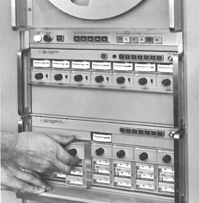 |
3950 System, Amplifier Plug-in |
We designed several different types of record and reproduce plug-ins. Each plug-in was designed to work at any selected tape speed. Each plug-in could accommodate three equalizers. The front of each equalizer was shaped like a wide pushbutton. Generally the transport tape speed was selected first then the equalizer that matched the selected tape speed needed to be activated by depressing it. Depressing any equalizer caused the unwanted equalizer to partially eject. It worked much like a push-button radio. Also any equalizer could be removed just by pulling on its front edge and a different one, marked with a different tape speed, installed in its place. The equalizer was a small printed circuit board with components mounted on it and a handle on the front.
There was no connector on the market available to connect the edges of the equalizer plug-ins to the plug-in mother board. When the equalizer was fully depressed we wanted it to make up to 16 connections and when partially ejected we wanted it to disconnect all connections. We wanted low insertion force but didn't want the equalizers to fall out. I designed a connector that satisfied those goals. The board entered the connector from the end rather than from the side which is the traditional method. The connector had contacts specially shaped and the mating contacts on the equalizer board edge were designed for easy insertion, board switching and board retention. On 1/13/65 I wrote a patent disclosure on this new connector idea. On 7/26/65 we applied for a patent and on 9/26/67 the patent #3,344,243 was issued on that special connector-switch design.
While in the tape group I surprised myself on the number of extrusions and plastic molded parts that I designed. The extruded parts were the mainframe top, meter insert, equalizer door, plug-in frame and bottom trim. Molded parts were the equalizer push-buttons, equalizer ejector levers, adjustment rod, and connector switch housing. The die-cast part was the plug-in front. After designing, building, evaluating, observing and working with model shop folks and tooling engineers on these parts, and learning about these various processes, I knew a lot more than when I started.
I'll digress a moment. I was most amazed and interested in the extrusion processes. I took a tour of Pacific Extrusion plant in Watsonville CA. In general extrusions should have a uniform wall thickness throughout the part but can be most any shape. The tool maker cuts a hole, the shape of your desired extrusion, in a piece of steel about 7" in diameter and 1.5" thick. The steel is hardened, inserted in a press and backed up with additional steel for non-interfering die support.
There is a billet of aluminum that is 7" in diameter and about 3' long that is inserted behind the steel die. The billet and die is heated to just the softening point of the aluminum. A hydraulic ram in a huge press then pushes the billet against the die and the softened aluminum flows through the die and retains the shape of the die opening. The thing that surprised me is that as the aluminum squeezes out of the die, a worker grips the hot extruding aluminum with a pair of vice-grip pliers as it leaves the die. He then pulls on the extrusion and runs along 100' or more of rollers to keep the extruded metal straight and under control until it cools. Without this control, the extrusion would bow, bend and be all over the place. It won't necessarily come out of the die straight and true. This process is repeated over and over depending on the quantity of extruded metal desired. While still warm, the extrusion is then clamped on each end. The clamps, which are 100' apart, are pulled away from each other to straighten the extrusion, then it's cut to manageable lengths. Extruding is a fairly crude process but it's surprising how closely that process will hold manufacturing tolerances.
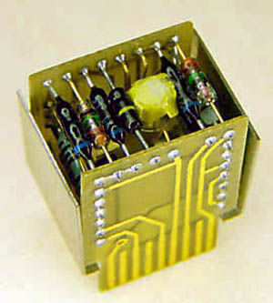 |
The critical FM oscillator. . . a sandwich board design. |
For servicing our plug-ins it was necessary to have connector extenders and module support. I designed a plug-in and equalizer extender. With these extenders in place we could have the complete tape system operating and be able to service any appropriate inoperative circuit.
This critical FM oscillator is shown to the right. . . a sandwich board design.
Our 3535A FM Record plug-in design had a voltage controlled oscillator which was the heart of the record circuit (operating as high as 216 kHz). It was a critical circuit so we designed it to operate in a temperature controlled oven within the plug-in. In our first prototypes this circuit worked flawlessly. Hans Westerby, an Electrical Engineer from Norway, and his leader, Joe Rolf, designed the electronics. I did the product design. We then built a pilot run of about 21 plug-ins and much to our surprise, some of the oven circuits started losing control and caused the ovens to turn full on. That made the circuit boards overheat and turn brown and some components failed from being too hot. When we discovered this, Joe was on vacation and Hans was on another important project so Walt told me to investigate the reason for this loss of oven control. I was both surprised and pleased. In my opinion, it was a circuit design problem. What do I know about oscillators, and oven controllers? I went forward as though I knew what I was doing.
I started an investigation and it didn't take long to discover that an overloaded transistor was experiencing thermal runaway. That happens when a transistor gets a signal to turn up the heat and in doing so, it makes the transistor hotter which causes the transistor to turn up the heat more so the transistor gets hotter, etc. The cure for this problem was to use a better transistor and heat-sink for the controlling transistor so it would run cooler. When Joe returned from vacation he was quite surprised and annoyed that his oven controller design had this problem but pleased that we found a solution.
While working on the oven heater problem, Walt suggested that I run some additional tests on this plug-in to see what it would do in temperature extremes. I started with a 7-channel mainframe, just at room temperature. I ran turn-on and time tests on seven different plug-ins, taking data every ten minutes, recording the data and plotting graphs. I even took the instruments home over the weekend to continue running the tests. After running the tests over the weekend, I showed the plots to Walt the next Monday morning. He said, "You know what I think?" I said, "No Walt, what?" He said, "Your garage is drafty!" He was right. The plots were all over the place. Those tests were taken before we had a really good oven design.
I set up the experiment on my lab bench using a small environmental chamber that could be set to go to temperature extremes from 0 to 55 degrees Centigrade. I made thousands of measurements of voltage and frequency over the next four months while making adjustments in the design of our plug-in oven and the internal circuit board. Each set of measurements took the better part of a day. When temperature is involved it takes time to cool the chamber to 0º C and let it stabilize. Then take appropriate readings. Then heat up the chamber to 50º C, stabilize and take readings. Again taking readings at ten-minute intervals, then 30-minute intervals at various temperatures.
With Walt's help, we made a temperature controlled oscillator that varied only a small percentage (about 0.00125%) over that temperature extreme and we had no more thermal runaway problems. It was a lot of work, a memorable investigation and a rewarding learning experience for me.
There was one project that was another learning experience for me and I pursued it to broaden my knowledge of transistors and various semi-conductors. In the early 1960s Tektronix came out with a curve tracer for vacuum tubes. The Tektronix folks later designed and sold a semi-conductor curve tracer. We had a couple in our Microwave lab. As time went on and semi-conductors became more popular in new designs, I wanted to learn more about them.
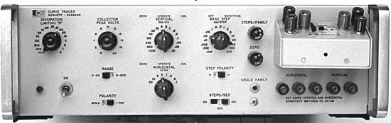 |
Never Seen Elsewhere - Bob's Transistor/Diode Curve Tracer |
I was quite taken by the curve tracer for vacuum tubes and the transistor/diode curve tracer. Both instruments were very useful to circuit designers and anyone wishing to analyze those components. To be able to see a family of transistor curves on the face of a cathode ray tube was just great. I had to learn more about those instruments. As a special project, I decided to build one. I thought that maybe HP could use a few curve tracers too. I discussed it with my friend Larry Johnson, a fine materials engineer, and he discussed it with his boss, Bill Myers, and they provided me with a number to charge part fabrication and purchases to. In between my tape system responsibilities I studied the Tektronix Transistor Curve Tracer manual. I soon realized that I only had to build about half of the Tek circuit because I'd be using an HP oscilloscope for the display.
I decided to build it into a 5" high by 16" deep Clement cabinet. Using that approach one could use either a 120B, 130C or 132A oscilloscope and it would fit right on top of this lower transistor test control box. For my special project, I designed a rear panel, main deck and front panel. I laid out the circuit boards that were designed using the "Sandwich" technology that I used in the 132A oscilloscope. I designed several different plug-in "front porches" that could accommodate different types of transistors. Two sockets on each porch for comparative transistor testing. I gathered all the parts together, assembled and wired two units. They both worked well. One was used in environmental test for component analysis and the other remained with me. It has been a useful instrument for characterizing transistors, diodes, neon bulbs, incandescent bulbs, resistors, capacitors and many unknown components.
There were a few product designs that I accomplished (See the Appendix at the end of PARTVII ) but some were not too exciting and pretty dull to write about. For the tape systems, I designed a Reproduce Track Selector. It was a quite simple product that would allow the user to select anyone of 14 tracks from the tape reproduce heads and feed the signal to anyone of seven different reproduce plug-ins. Its advantage is that a customer could purchase that lower cost unit rather than a second reproduce mainframe and seven more reproduce amplifiers with equalizers.
I was the product designer on a voice channel for the tape system. In addition to the 7 or 14 record/reproduce heads there was an additional head at the edge of the tape for a voice track. In running data logging experiments its beneficial to have voice annotation to narrate the experiment in progress. These tape guys think of everything. They sometimes would record a tone on the tape, using that audio track, and had a motor drive amplifier that would drive the capstan motor based on the frequency of the tone. That compensated for any variation in tape movement. Constant tape speed in recording was important but playing back the tape at the same speed it was recorded was more important. Any variation in tape speed, especially in FM recording and playback, resulted in changes in signals and measurements. These were really precise systems.
The Mountain View Division was another world. The HP merger with Datamec went quite well. They made digital tape systems and we made analog tape systems. In the lab there were about 20 digital guys and we had about 15 analog guys. At Mountain View the lab was located in the back corner of a large warehouse structure. The ceilings were about 20 feet high and had a cement slab floor. Most of us had lab benches, desks, filing cabinets and product designers had a drawing board. There were no tall walls separating different functions but there were short, 6' high walls. Adjacent to the lab was the shipping department. And then were the assembly folks, sheet metal fabrication and warehouse activities. Toward the front was marketing and office staff. One would hope that our lab environment could be mature, peaceful and quite for deep thinking. This lab was not quiet! One very disturbing occurrence was that each time the shipping department packaged up a digital tape system to ship to a customer, they sounded an air horn. This horn was from a diesel truck and operated from compressed air. It was an abrupt, long loud and unexpected blast that shook the building and made me jump out of my skin. It was just awful. It was good for manufacturing morale but a disaster for us lab guys and our nerves.
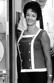 |
Throughout my tape recorder activities I was blessed with the able assistance of a dear lady, Erma Rhinehart. She was the most helpful and enthusiastic helper one could ever want. No task was too small or too large for Erma. As we worked together before the Datamec move I taught her how to lay out PC Boards, how to take drift data on the FM system, how to keep good notes and plot graphs. She could assemble, wire and solder as well as anyone. She was extremely helpful and pleasant to work with. She had been my assistant these several years. Upon the move to Mountain View, management decided to assign her to someone else. That, and some other issues, caused me to lose interest in magnetic recording.
Our fine leader and friend, Walt Selsted, actually moved to Mountain View with us but he left HP soon after this move. His new boss Gordon Eding was no John Young and Walt didn't want to be part of Eding's staff. So, Walt left and was replaced by Walt's long-time friend and X-Ampex guy, John Leslie. John was a pleasant guy but nothing like Walt. I can state that no one could replace Walt Selsted.
Shortly after our move to Mountain View Division my enthusiasm for magnetic recording was starting to wane. I was disenchanted mainly because Walt left HP and our group, they re-assigned my dear friend Erma to someone else and the air horns continued to blast unexpectedly. I stuck it out for a couple years at Mountain View because I was in the middle of an important project and wanted to complete it. I would not feel right about leaving any project unfinished. I remained until after production prototypes were finished and all documentation was complete and up to date.
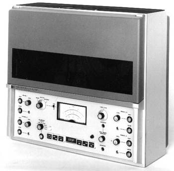 |
HP 3960A Portable Instrumentation Magnetic Tape Recorder |
This final project (3960A, B, C & D) was a very sophisticated portable instrumentation tape recorder. The project leader was Petter Brevik. A fine electrical engineer from Norway. Aki Awata, developed the casting for the tape transport, motor mounting, tape path and head mounting. I was the product designer for electronics support, front panel, instrument case, all the interconnecting wiring and plug-in circuit boards. I had the pleasure of working with a fine Industrial Designer, Kail Peterson, on the panel and case design. The design of this instrument was clean and fresh. It had four channels of record and reproduce and either direct or FM. It utilized 1/4" wide tape. It had a voice channel also. It was all transistor and tightly packaged. It could operate from 120/240Volts line voltage or 12 VDC.
This was a real packaging challenge. We had a lot of circuits to fit into a small package. When the instrument was removed from the case, it was designed to open like a book for trouble shooting and servicing the printed circuit "Pancake" motors, internal wiring and components behind the front panel. It was built into a custom designed instrument case. Clement's cabinet system would not work for this one. It was 16" Wide X 14" High X 7 3/4" Thick. It weighed about 50 pounds.
I had lots of fun working with Kail on the case. Since I had a table saw at home, I spent a lot of time cutting sheets of plastic and 1/8" plywood to make several different case mockups. We tried different colors and designs. The venting and cooling needed to be there but discreet. We just didn't want to punch holes at random but created a front and rear grill for airflow. We included a fold-away handle on the back and feet on the bottom. We had a flip up cover with a window to cover and protect the tape reels. The final case design was made up of sheet metal and assembled extrusions even though we considered a molded fiberglass design.
There is no question about it, I really learned a lot working in the tape group. It was a very rewarding experience in more ways than one. From this point on I feel very comfortable and knowledgeable working with and designing sheet metal parts, machined parts, castings, plastic moldings and extrusions. I really appreciate all the help I got from tooling engineers and various folks in the trades that helped broaden my experience and knowledge. I discovered that every day was a learning experience working in the lab at HP. Working with Walt Selsted and in his group was the right choice for me. The Magnetic Recording folks gave me five raises during these past four and one-half years. Completing this 3960A tape project and turning it over to someone else was good. While I enjoyed working with the folks at Mountain View and missed some of them greatly, it was really good to get back to the Microwave Division.
Toward the end of the 3960A project, I got a call from Rod Carlson, Lab Manager at the Microwave Division. I had very high respect for and had worked with Rod Carlson in the Scope Lab. When I met Rod in Scopes, he was project leader on the 185A Sampling Scope. He told me that he heard I was looking for a change and would I be interested in coming to Microwave? I said yes, and we arranged to meet for introductions and interviews with a couple of the Microwave mechanical engineers. Those interviews went well and I was hired and assigned to Brian Unter's Spectrum Analyzer section. I left Magnetic Recording on 1/31/69 and on the next day, I was really fortunate to be permitted to join Rod Carlson's Microwave Group.
On that last Friday at Mountain View Division It was a little sad for me to leave the Magnetic Recording group. There were some very fine folks there. The main person I would really miss was my dear friend and helper, Erma Rhinehart. We had worked together for several years. Before I left, she handed me a lovely card and small box with a gold desk thermometer inside. I couldn't speak, I had tears in my eyes and I just had to leave with a whispered "thank you." I still have the thermometer to this day, 42 years later, and a special soft spot in my heart for Erma.
Her card read:
 |
I was really lucky regarding the move from Magnetic Recording to Microwave Division. As the company grows, it seems that logistics and moves become more complicated. Each division looks at the bottom line and work hard to control all costs. I was afraid that I would have to leave my desk, lab bench, file cabinets and drawing board for my replacement and just move their contents. But after several discussions with management, I was able to move those furniture items along with myself. That saved me a lot of work and worry and saved HP a lot of wasted time and money. I turned all the project items, drawings and prototypes, over to the fellow that replaced me and moved everything I used on a daily basis.
One problem item that I moved was an adding machine that I selected and purchased from Sears (using HP money). I used it every day so I moved it along with all the other items. The folks at Mountain View Division wanted the adding machine back. Somehow they felt I should not have taken it. It was my machine, I thought. I even made a special bracket for it to mount to my drawing board for ease of use! I was the only one that ever used it. It was like they wanted my drafting pencil and erasers back. It only cost $67.00. I was really surprised but gave it to them a few days after my move. Actually my replacement came to Microwave to pick it up from me. That was actually OK because the Microwave Division folks let me purchase a better adding machine. I guess I'll never understand management?