Evolution of Data Acquisition and Logging Instruments
during the 1960 to 1980 Period


We didn't cover the Data Logging products manufactured by HP during the previous period of this Quick Tour, 1939-1960, because HP had virtually none in that period. On the other hand, it could be interesting to some of our readers to learn about the origin of the Data Logging product line at HP. In fact, this product line, like the digital voltmeter one, mostly came from the DYMEC Company, formed by HP managers in 1956, and which became an HP Division in 1959.
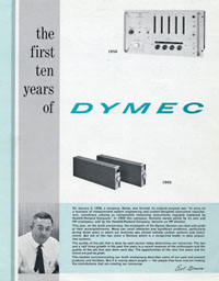 |
For those who want to learn more, here is an interesting document edited in 1966 and titled "The First Ten Years of DYMEC ". Its reading gives a lot of insight into the way Hewlett Packard made its entry into the digital instrumentation, and computer age.
Click on the link below for a PDF of the document titled "The First Ten Years of DYMEC ".
"The First Ten Years of DYMEC " - PDF File (4.8 Mb)
The first product line to be converted to digital at HP was the Electronic Counter line, designed and produced by the Frequency & Time Division. Consequently, it was the F&T Division which was the first to recognize a serious need for instruments which could record the data acquired and displayed by a Frequency Counter. . . No technician could write as fast as a digital counter could measure! Nor could a technician be available hour after hour for a test running for a long period.
The result of these considerations was the Model 560A, introduced in 1956, and described in the March 1957 issue of the Hewlett Packard Journal. The immediate commercial success of this innovative instrument would generate a new series of slightly different models. They have different capabilities to accommodate the growing variety of instruments from which digital data could be recorded. The staircase voltage method of transferring data from the digital (NIXIE) displays seemed unusual, but cleverly required only a single wire per digit rather than 4 that were later used for BCD connections.
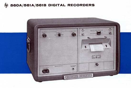 |
| The HP 560 Series in the 1959 General Catalog Courtesy of Hewlett Packard Company |
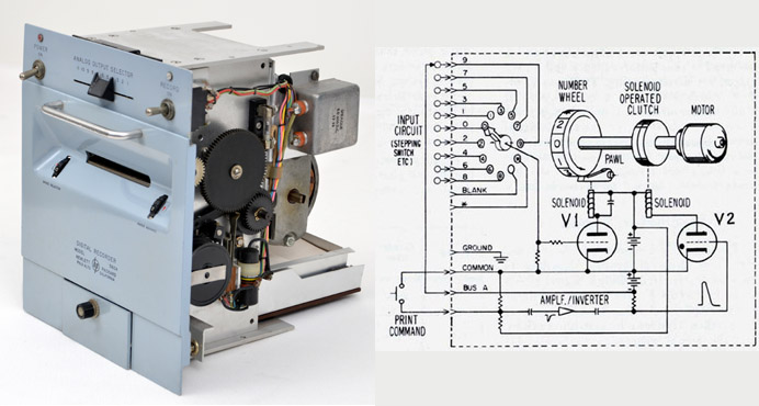 |
| The HP 560A out of its cabinet --------- On the right, a simplified schematic of the Wheel-Positioning, Print Command Circuit of the HP 561A/B |
Basically, the Recorders consist of a motor-driven print mechanism with inked ribbon, printing paper, eleven identical number wheels and eleven circuits which positioned the number wheels according to the count appearing on an associated electronic counter.
The Model 560A featured a printing speed of five, 11-digit lines per second. The 11-digit line allows secondary or coding data to be entered simultaneously with counter primary data. For example, several columns might encode the time of the data printout. Since the recorder is literally a slave to its associated input, the recorder accuracy is the same as the accuracy of the data gathering input.
In normal electronic operation, the 11 number wheels are locked in position while the counter is counting. At the end of each counting period, the staircase voltage generated during the count by each decade in the counter comes to rest on the step or voltage level corresponding to the digit displayed by that decade. Inside each decade counter module is a resistive matrix arranged to create a voltage staircase, equal to 10 volts for each advancing digit, for a 0 to 100 volt total height. Recall that HP counters of that period had invented a photo-resistive matrix on a ceramic plate that fitted against the 10 tiny neon number display of early decade modules. This photo-conductor plate then encoded voltages to run the popular Burroughs NIXIE (r) tubes.Each staircase voltage step is sent to the recorder along with a print command pulse which occurs at the end of the count period.
The command pulse then initiates a mechanical scanning cycle during which the number wheels are simultaneously positioned according to the staircase voltage levels received from the counter decades and locked in position. At the end of the scan cycle a print of the data is made, and the paper automatically advanced to display the printed count.
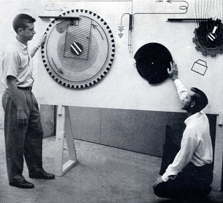 |
| F&T Division Manager Alan Bagley,( left) and Ed Hilton shown operating
mechanical mock-up of Model 560A Print wheel mechanism. From a 1955-1957 supplement to the 1954 anniversary issue of WATT'S CURRENT. Courtesy of Hewlett Packard Company |
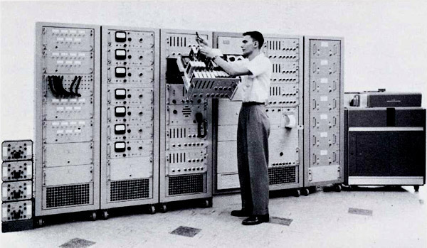
During the period from 1957 to 1966, which was prior to the first HP computer as well, the design and production of Data Acquisition Systems was the domain of the DYMEC company. They worked on mostly custom systems, specifically designed and contracted to fit a required customer need. It could be very large system like the 6-bay system shown below, supplied to Boeing for multi-channel pressure measurements. Pressure data from fifty transducers was recorded simultaneously on magnetic tape. The aircraft and space programs of those years often had system test procedures that required multiple channel measurements of vibration or stress testing of mechanical performance. Sometimes hundreds of channels. An entire measurement industry had grown up for this work, which included telemetry transmission and logging of actual flight tests. The Sanborn Company which HP acquired in 1961 participated with systems that competed in that specialized market.
Another product with which DYMEC contributed to the HP catalog by the end of the 1950s, was the Magnetic Tape Recorder; a reliable process to store large amounts of test data, easy to retrieve and analyze. A long time before magnetic tape was used as a central device for computer digital data storage, the analog Magnetic Tape Recorders were the only way to store large flow of analog data. The most common usage of this technique was for the entertainment and studio audio tape recorders, but highly sophisticated versions of this technology gave birth to the Instrumentation Tape Recorder.
As an example, John Minck remembers his first big-time engineering job out of Notre Dame in 1952. It was full scale test for atom (hydrogen) bomb tests in the Pacific at Eniwetok Atoll. The test program involved ground acceleration sensors, air over-pressure sensors, wind speed sensors, temperature, etc. It entailed instrument bunkers along a 20-mile blast line from ground zero, on maybe 6-8 of the smaller islands of the atoll--which was 30 miles in diameter. Each bunker handled about 40 channels, with the primary data on galvanometer traces on photographic film, with backup channel recording on Ampex 14-channel analog tape recorders. The backup to tape was for two reasons, 1) because the amount of potential radiation blackening of the photographic paper was unknown, and 2) the reliability of tape to retain data for VERY EXPENSIVE one-time events.
 |
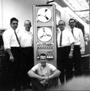 |
This photo (L-R) shows Girdner, DeVries, Overton, 3950 System, Selsted and Ainsworth. |
Starting about June 1964, a small Recording Group consisting of Bill Girdner and Walter Selsted was formed. As time went on, Walt's tape group expanded, and later merged with a small Digital Tape Instrumentation Company HP purchased called Datamec located in Mountain View. Selsted was a long-time designer with the Ampex Company in Redwood City, CA, and brought that significant instrumentation experience to HP.
Bob DeVries who was the industrial design engineer in the Magnetic Recording Lab recalls:
"Our first system was a high frequency (1.5MHz) system called a 3950 Series. The second one was a low frequency (300kHz) system called a 3955 Series. These were large systems mounted in cabinets seven feet high by a couple feet wide and deep. A typical system was made up of tape decks that could accommodate either 1/2" or 1.0" wide tape. Tape 1/2" wide enables a record/reproduce capability of 7 channels and 1.0" wide tape has the capability 14 Channels. We could accommodate reels of tape either 10" or 14" diameter.
The systems included a special housing mounted in the transport for pre-amplifiers and below the transport we had cabinet/s for plug-in record and reproduce electronics. These electronics could either be FM Record and Reproduce and Direct Record and Reproduce as required. Even these Record and Reproduce electronics had little equalizer plug-ins that were designed to match the selected tape recorder speed. The transports could run at 1.75, 3.5, 7.0, 15.0, 30.0, 60.0, and 120.0 inches per second tape speed. We had equalizers for each speed and for each channel. The system was designed to be very versatile, interchangeable and custom built to satisfy the customer's needs. Our pilot run of the 3950 system included 13 each record and reproduce mainframes, 88 each record and reproduce plug-ins and bunches of equalizers. I don't know how many transports but would guess 13 also.
An impressive example of the 1.5 MHz system is that at a tape speed of 120"/Sec the bandwidth of the system was flat from 400 Hz to 1.5MHz. That means that the entire AM broadcast band could be recorded all at one time on each of seven or fourteen tracks. The AM broadcast band could be recorded by connecting an antenna to the input connector of Channel One. To later listen to it in playback one could use an AM radio connected to the output of Channel one and just tune to the AM station of choice. That experiment only used the bandwidth from 500kHz to 1.5MHz of that channel. The band below 500kHz could be used for something else. That experiment uses only one channel of the seven or fourteen channels available. These systems could record and store a lot of data."
The HP Magnetic Recording Lab chapter inside Bob DeVries's HP Memory story is here, and the full story here on this website. It's a must read. (use your browser back-button to come back here).
 |
For those who want to learn more, the "Magnetic Tape Recording Handbook," edited in August 1967, gives an in-depth analysis of the various technologies involved in the design and manufacture of the Instrumentation Magnetic Tape Recorder.
Click on the link below for a PDF of the document titled "Magnetic Tape Recording Handbook".
"The Magnetic Tape Recording Handbook" - PDF File (4.8 Mb)
 |
The HP 2116 "Instrumentation Computer" HP Memory Project Collection |
In 1966, a variety of tools had been designed and were available to satisfy a number of data logging problems. But the logged data was displayed, printed, or stored "AS IS," in the same format that it was outputted by the instrument taking the data.
The birth of the Computer introduced a PROFOUND new capability to the world of data acquisition and processing. Besides collecting data, the computer can manipulate the data. It can also make decisions based on the instrument readings and perform some process function by way of relays for example.
In electronic engineering, the engineer normally would prefer to have the flexibility to convert the captured data units into other formats and computed results. Even if such kind of calculation could seems very simple, doing it hundred times each second was a capability available on the earliest HP computer. And, at HP, for many strategic reasons, not to be discussed here, the first HP computer was designed as, and named an "Instrumentation Computer". This decision can be seen upon opening the front door, where 14 input/output circuit boards were mounted, each on connecting to its own measuring or signal source instrument.
Starting in 1966, the HP 2116 computer opened the market of data processing to Hewlett Packard. While it was rolled out as an instrument computer and controller, several creative customers quickly found that it could operate as a server for a time share system with multiple Teletypes and GE Basic software.
For more information on the HP 2116, and its early successors, go to the "Early Computer" chapter, in this same period of the Quick Tour. (Use your browser back-button to come back).
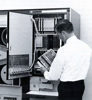 |
External devices are interfaced by inserting the appropriate interface in the model 2116 computer card-cage |
After the 2116A introduction, immediate successors were lower performance, lower cost computers, directly derived from the 2116 concept but built to expand the customer market. The success of the HP2116A generated a large demand in general data processing. The 2115A was introduced in 1967. The 2114A, introduced in 1968, was an even more economical version of the 2116A, which came standard with 4096-word or 8192-word of magnetic core memory. The 2114 can be considered as the first HP computer directly targeting mainstream data processing applications, even if HP was still referring to its computers as "instrument controller" until the introduction of the first HP3000 mid-sized computer. For readers only familiar with massive memory capability in tiny smart phones, it will come as a shock to hear that optional extra memory which could be purchased for the 2116A was $1 PER WORD. The memory was ultra tiny ferrite donuts, threaded by hand, X-direction, Y-direction and 45-degree direction. And most customers were pleased to buy that option.
The main problem for data logging application with this first generation of HP computer, was the interconnection with the variety of instruments already available to build electronic test systems. Even if the BCD interface was one of the most common, many instruments would need a dedicated interface printed-circuit board to be inserted in the computer card-cage. Data input/output exchange with peripherals of the time, teleprinter, punched tape, magnetic tape, disc, would each need a different and unique type of interface.
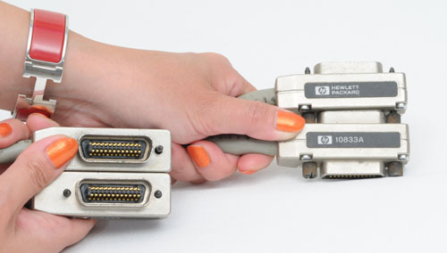
Without question, this was a good reason for HP to be the first to develop an advanced concept for the general-purpose interconnection of instruments into a digitally-controlled system. The interface system that made this possible was introduced in 1972 at HP, and was called the Hewlett-Packard Interface Bus. Later, out of a concern that HP should lead a group of instrument manufacturers to adapt a common standard, and working through the IEEE sponsorship, it became an IEEE standard in 1975. The January 1975 edition of the Hewlett-Packard Journal gave a complete description of the HP-IB design strategy, and introducing, at the same time, several HP-IB programmable instruments and a quantity of new modular accessories filling in the gaps for automated instrument systems construction.
The HP-IB would became from this time forward the backbone of every automated system exchanging data between instruments and computers. In that same period, the HP Desktop Computer division was modifying their computers to become instrument controllers and prepared comprehensive and easy-to-use programming software.The majority of instruments developed after 1975, were HP-IB compatible as a standard feature or as a low-priced option. By the end of the seventies, more than 200 HP instruments were HP-IB compatible, thus giving HP a considerable leadership in the automated electronic systems design. Many HP-IB, interconnected systems, are still in use today in the industry, a testament to the far-sighted design strategy of those designers.
 |
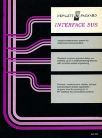 |
Cover of a 1975 HP-IB Marketing Document |
As soon as 1975, a number of HP-IB compatible instruments, and accessories, were already available for do-it-yourself HP-IB system solution.
The April 1975 marketing document on the right lists those systems. (PDF 1.4 Mb)
Among them, at least a dozen instruments, newly introduced in 1975, were designed to help the engineer in the construction of custom automated system, and dedicated data loggers. Some of the most important of them, shown on the picture below, were:
The Model 59303A Digital-to-Analog Converter accepts up to 15 ASCII-coded digits serially, and produces an analog voltage within a range of ±10V equivalent to three consecutive digits selected from the string. Among other uses it can be used to convert the digital output of a counter or a DVM to an analog voltage for driving a strip-chart recorder or an X-Y plotter.
The Model 59308A Timing Generator functions either as a digital delay generator (timer) or as a precision time marker generator (pacer). As a timer, the Generator counts down crystal-controlled 1 MHz pulses and, following the receipt of an input trigger, generates an output pulse when the selected number of 1 µs time increments has elapsed. In the pacer mode, the generator produces a pulse at a customer-set delay, on and following the receipt of a trigger. It may also be used for time interval measurements. It has an internal six-digit (decimal) counter that totals the number of output pulses produced since a trigger was received.
The Model 59309A ASCII Digital Clock gives absolute time in seconds, minutes, hours, days, and months. When connected to the HP interface bus and triggered to talk, it outputs the time of day onto the bus. The Digital Clock is a precision instrument, using a 1 MHz quartz crystal resonator in its master oscillator. The aging rate of the crystal is 5 parts in 106 per year. The clock can also be driven by an external frequency standard of 1, 5, or 10 MHz.
The Model 3495A Scanner switches several analog inputs one by one to a single instrument for measurement and recording. The 3495A can serve as a programmable switch for actuating external processes or for distributing power and/or signals. It can also connect more than one channel at a time so it is able to make the multiple connections needed for four-wire resistance or floating bridge measurements. Where there may be more than one measuring and/or stimulus channel to be connected to a multiport device, the scanner can also be configured to make the multiple switch closures needed for microwave matrix switching.
The Model 59306A Relay Actuator has six form-C relays for control of equipment ranging from microwave switches to environmental chambers. The relays have both normally-open and normally-closed contacts and can switch up to 25V at 0.5A.
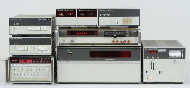 |
| On the left, top to bottom: HP 59306A Relay Actuator - HP 59307A VHF Switch - HP 59401A Bus System Analyzer Middle, top row: HP 59309A Digital Clock (x2) - HP 59308A Timing Generator. Middle-middle row: HP 3490A Digital Voltmeter. Middle Bottom: HP 3495A Scanner. On the left: HP 5150A HP-IB Alphanumeric Thermal Printer HP Memory Project Collection |
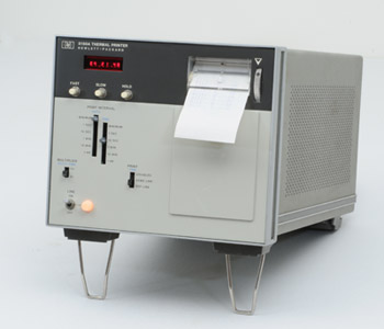 |
The HP 5150A |
The Model 5150A Alphanumeric Thermal Printer was also introduced in 1975, and listed in the marketing document discussed above. It was another instrument for do-it-yourself HP-IB system solutions. However, the 5150A printer is not limited to recording data in systems using the HP Interface Bus. The printer works as well with the older BCD instrument interface, thus permitting the customer to mix HP-IB, and Pre-HP-IB instruments in the same custom system.
Besides accepting the widely-used BCD data from a variety of instruments or ASCII-coded characters from the HP-IB or other ASCII-coded data sources, the new printer can also control the timing of data acquisition and direct the sequential acquisition of data from several sources. It can also print the time of day on the data record.
In its simplest application, the new Model 5150A can do as earlier printers have done; log data from a dedicated companion instrument. When used with the HP Interface Bus and operated in the "listen only" mode, it accepts all data appearing on the bus. When it senses the LF command, it prints the most recent 20 characters (or fewer if less than 20 have been received since the last LF command). In the "addressable" mode, it accepts data only when addressed.
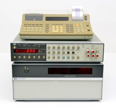 |
The HP 3051A, Low-Cost Programmable Data Logger HP Memory Project Collection |
The Model 3455A Voltmeter is combined with a scanner and a calculator by exploiting the HP Interface bus, forming a versatile but inexpensive data logging system, designated Model 3051A.
Under control of the calculator (Model 9815A), the scanner connects signals from transducers and other sources one at a time to the voltmeter's input. The voltmeter measures the signal level (or resistance) and presents the result to the calculator which stores the result on a magnetic tape cartridge for later analysis or, if desired, converts the data to the desired units before storing It. Up to 18,000 six-digit readings can be stored on a single removable cartridge.
The data-logging system enables data from widely dispersed monitoring points to be gathered at a central station for immediate interpretation and further instructions or action.
Besides collecting data, the calculator can manipulate the data, such as linearizing thermocouple readings. It can also make decisions based on the voltmeter readings and sound alarms or perform some process function by way of relays in the scanner. Up to 40 channels can be handled by the scanner, and the system accommodates two scanners, giving the capability for 80 channels.
The system was designed so it can be immediately installed by a user who has had minimum programming experience. A prerecorded tape cartridge supplied with the system asks the user a series of questions by way of the calculator's alphanumeric printer. The user responds with a few keystrokes, usually a 1 for yes, a 0 for no, or a numerical entry such as the range of the voltmeter for a particular channel. Once all the information is in the calculator, a blankcartrldge is Inserted In the calculator, and the program, now properly sequenced, is stored on the "test" cartridge from which it can be loaded into the calculator anytime that program is to be used.
As a user becomes familiar with the calculator, he can write short subroutines that can be assembled as part of a program by the relocating loader supplied with the system. Writing a program is simply a matter of designating the keystrokes for solving a problem, just as with a hand-held programmable calculator. Branching, conditional instructions and flag manipulation enable the system to make intelligent decisions about the data. FOR-NEXT loops permit program sequences to be repeated a predetermined number of times.
Since the system components are interconnected by means of the HP Interface Bus, it is relatively easy to add other instruments or peripherals, such as the Model 9871 A Impact Printer that can present results in graphic as well as printed form.
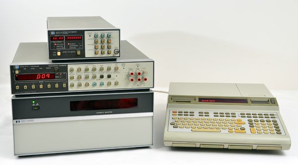 |
The Model 3052A Programmable Data Acquisition System, controlled by a Model 9825A Calculator, also includes a Model 3455A Voltmeter and a Model 3495A Scanner. It has all the capabilities of the Model 3051A Programmable Data Logger, described above, plus much more, such as low-frequency waveform analysis, and three-dimensional plotting.
The Model 3455A Voltmeter gives the system high accuracy, high sensitivity and excellent noise rejection with a maximum system reading rate of 19 dc channels per second with 1 µV resolution, or 10 channels per second when measuring ac volts and 11 on ohms (16.5,9.5, and 10 on 50 Hz power). Model 3437A System Voltmeter gives the capability for high reading rates - up to 125 channels per second with 0.1 mV resolution and more than 4900 3 1/2-digit readings per second on a single channel.
The Model 9825A Calculator brings to this system many capabilities formerly found only in computer-based systems, from transducer linearization to statistical analysis. It uses a high-level, formula-oriented programming language (HPL) designed for controller applications as well as for data processing. The user communicates with the calculator by the way of the typewriter-like keyboard and the calculator responds with its alphanumeric display and printer, giving immediate feedback on errors from improper syntax.
Manuals supplied with the system give complete details on starting up the system and programming it. Also included are pre-recorded tapes that have subroutines for operating the instruments, thermocouple linearization routines, data plotting routines, and a number of application routines that are modular in structure, allowing the user to modify them easily for his particular applications. Among the application routines is one for analysis of waveforms sampled by the Model 3437A Voltmeter. It uses a Fourier algorithm for identifying and measuring harmonics as small as 60 dB below the fundamental, besides giving waveform amplitude and frequency.
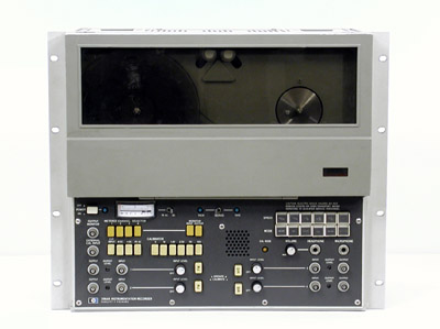 |
The HP 3964A Instrumentation Tape Recorder HP Memory Project Collection |
As late as the end of the 1970s, internal computer memories were far too small to be able to serve as measurement data storage, especially those data streams generated by wideband signals. Auxiliary storage was the answer.
Consequently, even in 1977, the Instrumentation Tape Recorder like the HP 3964A, shown on the left, was introduced as a new product in the general catalog. One key feature was its desirable portability, and yet impressive data performance.
The Model 3964A, 4-channel, utilizing a 1/4-inch (6.3 mm) tape width format, was designed to meet the demand of the individual and OEM users.
The 3964A has one four-track record head, and one four-track reproduce head using in-line track configuration. Possible tape speeds are the following: 1.19, 2.38, 4.75, 9.52, 19.05, and 38.10 cm/s. The 3964A passband is 70 to 64,000 Hz, at maximum tape speed.
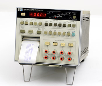 |
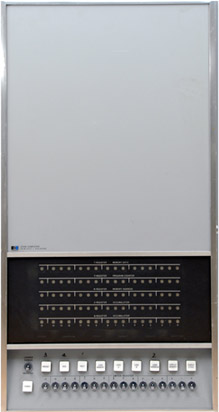
The HP 3467A |
Our last listing in this 1960-1980 period is the HP 3467A Data Logger which was introduced in the 1979 general catalog.
By combining the attributes of a 4 1/2 digit multimeter, a thermometer, a 4-channel scanner, a printer, and a microprocessor, the 3467A was designed as a benchtop, stand-alone instrument, and a time-saver for the everyday design engineer.
Capable of handling a major part of the measurements required during the course of a typical electronic design effort, this self-sufficient instrument measures AC and DC voltages, resistance, and, with external thermistors, temperature. It has a four-channel scanner, a thermal printer for permanent records, and an internal timer that allows unattended measurements. The 3467A requires no external control or I/O, yet it can perform computations on measurement data under pushbutton control.
The nucleus of this instrument is a 4 1/2 digit, autoranging multimeter, basically similar to the HP Model 3466A Digital Multimeter. The printer is a compact, moving-head, dot-matrix, thermal printer similar to those used on the HP-91 and HP-97 Calculators. Scanning is by means of reed relays. A microprocessor provides the communication between the multimeter, scanner, timer, and printer.
Inclusion of a microprocessor allows math operations to be implemented. Among other things, these make it possible to linearize and convert readings of thermistor resistance measurements into readings of temperature in °F or °C. Other operations performed with the math functions involve the use of channel 4 as a reference, designated "Y." Any of the other three channels, designated "X," may then operate on the reference so measurement results can be presented in the most desired format.
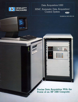 |
A technical data sheet published in February 1981 showed the HP outlook for the evolution of data logging systems that customers could expect at the beginning of the 1980s.
Click on the link below for a PDF of the document titled "Precise Data Acquisition With the Power of an HP 1000 Computer ".
"3054C Automatic Data Acquisition / Control System" - PDF (4.3 Mb)
