
The Data Domain Transition,
Introduction, by Chuck House
A decade after the Hewlett-Packard company was launched in 1939, communications test tools - for the frequency domain - were 96% of HP revenues. But HP was primarily an Audio/Video test equipment company - 84% of revenues came from low-frequency tools for radio and television design and trouble-shooting. Microwave tools were a mere 12% of revenues. A decade later (1959), microwave tools for the AT&T national communication network were two-thirds of HP's frequency domain revenues. Meanwhile, a new category - the time domain , with digital counters and oscilloscopes - had emerged, with a quarter of HP's revenues. David Packard left HP for a job in Washington D.C in January 1969; he would never again directly manage at HP. But the acquisition strategy in his last decade totally transformed the company. The entire frequency domain was down to forty percent of the company, even as it quadrupled in absolute magnitude. Time domain equipment gained 50 percent vis-à-vis frequency domain products, but was still just a quarter of the corporation's total revenue. The momentum was in the scientific instrumentation acquisitions and activities in new areas (medical, analytical chemistry, recorders, and components) that was suddenly a full one-third of HP revenue (this was still instrumentation; computers themselves were only 4% of the total). When Dave Packard left HP, the company was just launching the first desktop calculator, the revolutionary HP9100A. The next eight years would dwarf earlier transformations at HP. Scientific instrumentation and scientific computing became sixty percent of HP, and a new entrée - business computing - weighed in at ten percent. The old standbys - frequency and time domain instruments - shrank to just a quarter of HP's business. Such changes in the HP revenue model had two interesting consequences. First, most of the company's focus shifted from instrumentation to computing - what some would later call "the tail wagging the dog." But in terms of designing instruments, the old Hewlett maxim of "the next bench syndrome" was being challenged heavily. Digital Circuits confronted designers and troubleshooters with measurement problems that differed in many ways from those in analog circuits. Facing the problem of measuring the signals flowing in the first generation of integrated circuits, HP's two leading time domain divisions - the Santa Clara (CA) Division and the Colorado Springs (CO) division - each embarked on a serious of exploratory tools to help digital designers. Over a brief period from 1969 through 1973, Logic Probes, Clips, and Analyzers appeared - tools that became known as data domain instrumentation. By 1977, when HP fully arrived in computing, the Logic lines were solidly established. The Logic Analyzer passages below show this evolution in product form from the earliest days. An essay, "Logic State Analyzer Birthing Pains," by Chuck House," describes some of the excitement (and difficulties) of the day from the Colorado Springs viewpoint. HP (and then Agilent) became key suppliers for this field - ultimately shipping nearly six billion dollars of equipment over the next forty years if Program Development Systems are included, about half of all that worldwide competitors supplied. Steve Leibson, who has authored other pages in the HP Memory lore, has remarked that very few dynasties have existed in electronics over the last fifty years, but certainly the Intel microprocessor chips, the Apple Macs and Logic Analyzers from HP / Agilent would qualify.
Chuck House
|
As usual, this "Quick Tour" will limit the story to a short overview of the various tools and instruments which defined the major steps in the evolution of this important HP product line. But for those who would like to read an in-depth history of the Logic State Analyzer, they will find it already on this website. Chuck House, the accomplished author of "The HP Phenomenon," spent a large part of his career at HP managing the team who created the Logic Analyzer concept. The Birthing of the Data Domain (he coined the term), and the Logic Analyzers play out over a cast of fascinating personalities; of Chuck's management, his design customers, his technical mentor gurus, and his engineering team. House's memories of this HP period are revealed in this writing:
"Logic State Analyzer Birthing Pains," by Chuck House
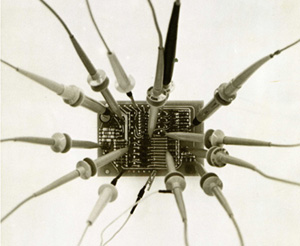 |
This amount of digital data probing should help understand what's happening on the PC Board. |
Before the Birth of the First LSA,
By the end of the 1960s, Digital Circuits confronted designers and troubleshooters with measurement problems that differed in many ways from those in analog circuits. Facing the problem of measuring the signals going-in, or coming-out from the first generation of integrated circuits, the most immediate need was to watch more signals simultaneously with a multi-trace oscilloscope. Engineers involved in logic circuitry measurements were hopeful that by combining two four-channel vertical amplifiers, they could gain some understanding of these new circuit devices. With eight channels, screen clutter was an issue, and the probing problems became physically daunting as well. It was more than that, since the INTERPRETATION of 8 pulse waveforms could drive an engineer slightly daffy.
The small size of this new generation of electronic components required a considerable probe size reduction for every instrument used in signal measurement. On the other hand, in many cases, servicing in particular, the huge quantity of information delivered by an oscilloscope turned out to be not necessary for a quick checking. The IC logic threshold voltages and switching characteristics being standardized, the checkout problem often reduces to questions like "Is the voltage on this logic line in the high state or is it in the low state?" Or "Are pulses present on such-an-such line?" In these cases the voltmeter and the oscilloscope give more information than is wanted.
From these considerations came the idea for the first tool dedicated to Logic Circuit tracing made by HP, the Model 10525A Logic Probe. The June 1969 edition of the Hewlett-Packard Journal described it in an article titled "IC Logic Checkout Simplified".
Many other models of Logic Probes, based on the same concept, would be introduced by HP during the 1970s. Some of them are shown on the picture below.
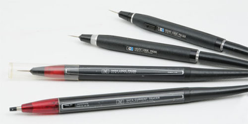 |
| Various Model of HP Logic Probes from the Early 1970s |
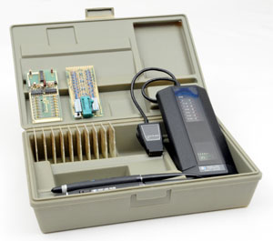 |
The HP 5011T Logic Troubleshooting Kit |
The HP 5011T
Logic Troubleshooting Kit
Some other kind of tools, fully dedicated to the analysis of integrated circuits were designed, and packaged into kits like the HP 5011T Logic Troubleshooting Kit shown.
The 5011T was a complete tool kit including a Logic Probe, a Logic Pulser, a Logic Clip, and a Logic Comparator.
These tools were designed to re-direct the troubleshooter's efforts toward circuit analysis rather than toward analyzing how to use analog tools to make meaningful measurements in digital circuits.
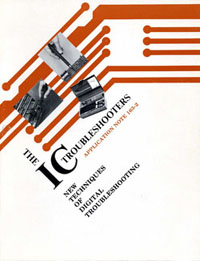 |
Cover of Application Note 163-2 |
To educate the final users with such new concepts, introducing the best possible new tool was not sufficient by itself. But providing all the necessary educative material was another major concern. And this kind of brand new technology education was one thing that Hewlett Packard was particularly good at.
Addressing this need, Hewlett Packard developed a line of digital circuit learning, and training tools. Among them a number of product, and application notes were published during the seventies. They were not only an in-depth user guide of a specific product, in most case they also included a basic course of all the necessary fundamentals for the best understanding of the techniques involved.
AN 163-2 is a good example, among the many others, which were generated by the birthing of the digital logic techniques. It's a 38-page, 5.6 Mb PDF file, downloadable here:
AN 163-2 - "New Techniques of Digital Troubleshooting"
 |
 |
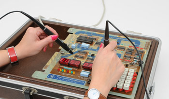
Using the 10525T Logic Probe, and 10526T Logic Pulser |
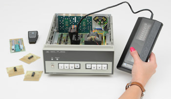
Using the 10529A Logic Comparator |
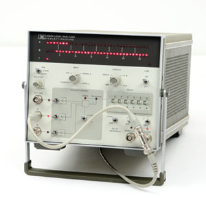 |
The HP 5000A Logic Analyzer |
The First LSA
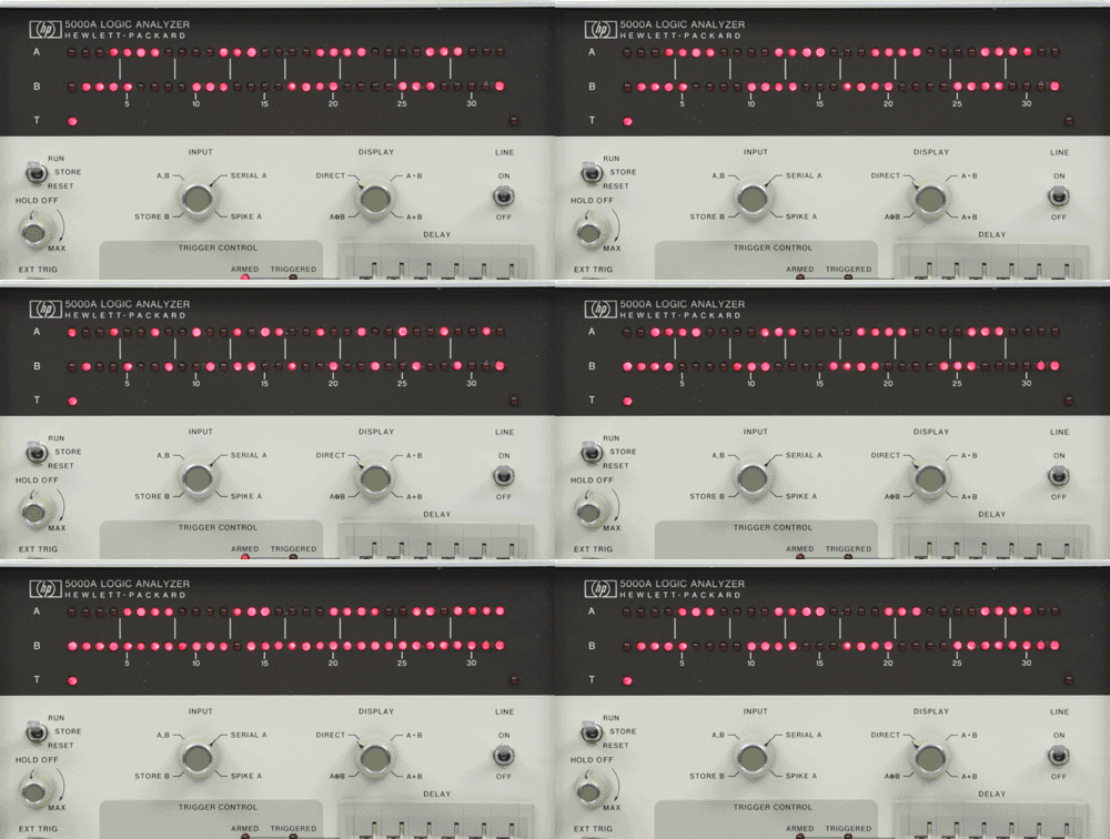
Introduced in the October, 1973 issue of the Hewlett Packard Journal, the HP 5000A was presented as "A New Instrument for Observing Logic Signals." The 5000A displayed digital data occurring at its two channel inputs on two rows of 32 light-emitting diodes. A lighted LED indicates a logic HIGH level. Other LED's indicate the trigger point, input conditions, arming, and triggering. Several display modes helped solve a multitude of digital measurement problems in design and troubleshooting.
Even if presented as a standalone Logic Analyzer instrument, reading the HP Journal article clearly reveals that the 5000A was first of all a sophisticated digital trigger to be used with a companion oscilloscope.
But it was not a long wait for the introduction of the next generation of Logic State Analyzer, which integrated the required specific triggering functions inside a dedicated oscilloscope mainframe.
 |
 |
The HP 1601L |
The HP 1601L
Logic State Analyzer
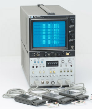
The HP 1601A was introduced in the January, 1974 Hewlett Packard Journal as "A NEW WINDOW" into the world of digital processes!
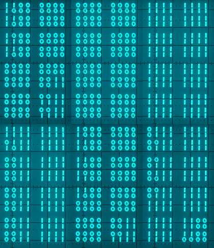
The Model 1601L Logic State Analyzer, displays 16 consecutive 12-bit words as "1's" and "O's" in 16 rows, just as logic data or truth tables are presented in textbooks. The tabular display of consecutive words provides an overall view of system operation that makes it far easier to trace information flow than would be possible with an oscilloscope or other traditional test instrument.
The 1601A Logic State Analyzer was packaged in a drawer which fits into HP oscilloscope mainframes of the 180 family. When bought as a complete system, HP 1601L, a dedicated mainframe HP 182C was delivered with the 1601A, as well as a completely new designed probing system.
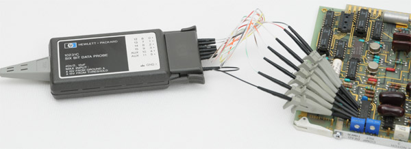 |
| The new probing system introduced with the 1601L Logic State Analyzer had a clever probe tip design, which enables probes to be attached to adjacent pins on standard DIP IC packages that have as little as 0.5 mm clearance between the package and the leads |
New Concepts Often Do Not Gain Easy Acceptance,
In this evolutionary period, engineers were far from enthusiastic users of logic analyzer. The concept was not yet accepted as a common practice. The oscilloscope remained popular, although design thought leaders were seeing the horizon of the new concepts.
By presenting digital signals in the time domain, oscilloscopes can help find the sources of problems caused by propagation delays, transient spikes, noise, ringing, and inadequate pulse amplitude in digital systems. However, isolating a short segment of a long digital sequence for detailed analysis is very difficult if not impossible with a conventional scope. To provide the trigger recognition needed for oscilloscope in the analysis of digital sequences, a number of accessories were developed by Hewlett Packard.
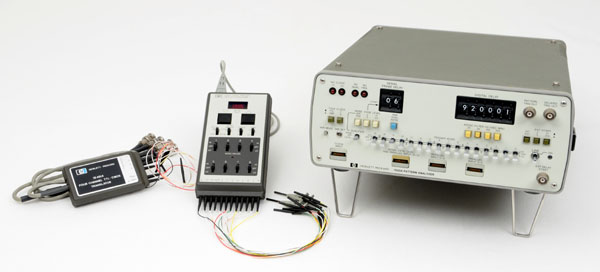 |
| From left to right HP 15451A Four-Channel Trigger - HP 1230A Eight-Channel Logic Trigger with Digital Delay HP 1620A Sixteen-Channel, Parallel or Serial Monitor |
The most basic of these trigger recognizers were the HP 10250-series Trigger Probes, which look like the one shown on the left in the picture above. These probes monitor up to four digital channels, and whenever the bits appearing simultaneously in the four data streams match the pattern established by the probe's switches, the output goes high, providing a trigger suitable for an oscilloscope or other instrument.
The Model 1230A Logic Trigger, (center in the above picture) augments this basic trigger recognition to eight-channels, and by adding digital delay, make it possible to move the observation "window" up to 9998 clock pulses down-stream from the recognition word.
The most versatile logic trigger is the HP Model 1620A Pattern Analyzer. This instrument operates with either parallel or serial data streams. In the parallel mode the 1620A monitors up to 16 lines at bit rates up to 20 MHz. In the serial mode, Model 1620A generates a trigger when a sequence in the incoming bit stream matches the pattern set on the front-panel switch register. The serial mode is useful for triggering on specific portions of long digital sequences like those encountered in disc memories.
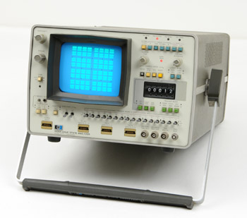 |
The HP 1600A Logic Analyzer |
The HP 1600A LSA
Slowly but surely, engineers developing digital systems found themselves more concerned with word flow than with analog waveforms. With the insight provided by the previously-mentioned HP 1601L, it became much easier to trace data flow and track down problems in digital systems. Digital designers who have had the opportunity to use this instrument find it indispensable for analyzing and troubleshooting the digital systems on which they were working.
In August, 1975, two years' experience with the Model 1601L had uncovered a number of additional capabilities that such an instrument might have. These capabilities were incorporated in a new logic state analyzer, Model 1600A, which worked with or without a companion instrument, Model 1607A.
Basically, the Model 1600A works like the earlier Model 1601L: digital data appearing in parallel on several different lines is monitored through a multi-probe system and clocked into the instrument in synchronism with the clock or other pulses from the system under test. The new Model 1600A Logic State Analyzer broadens this basic capability by being able to look at 16 lines simultaneously, four more than the 12-bit capability of the earlier Model 1601L. When working with Model 1607A, Model 1600A can look at and display data appearing at 32 points.
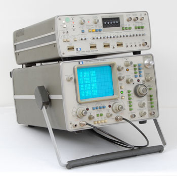 |
The HP 1607A coupled to a 1740A Oscilloscope |
The HP 1607A
The Model 1607A Logic State Analyzer was designed with a dual purpose in mind: (1) to serve as an extension of the Model 1600A Logic State Analyzer and (2) to function independently as the logic state input for laboratory oscilloscopes.
Like the HP 1600A, the Model 1607A was introduced in the August, 1975 Hewlett Packard Journal. Models 1600A, and 1607A Logic State Analyzers can work together to monitor and display 32-bit words, or work with independent clocks to examine the interaction between digital machines. In this case, the combination of the two instruments is known as the Model 1600S.
But the Model 1607A, having most of the capabilities of Model 1600A, can also work by itself using an oscilloscope or a CRT monitor for the display. Such a configuration, using a HP 1740A as a companion oscilloscope is shown on the picture.
Old Habits Die Hard,
Three years after the introduction of the first Logic State Analyzer, HP R&D Labs, Marketing Services, and Field Sales Force, still had to create technology teaching efforts to convince their customers of the importance of the Data Domain Revolution. They multiplied the number of seminars, technical data sheets, and application notes, to help engineers change their thinking about logic circuitry design. The Sales-aid document shown below is a good illustration of this concern.
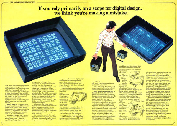 |
| "Join the Data Domain Revolution," a 1975 Commercial Document Click in Picture to download the PDF |
Two Decades . . . Three Revolutions!
From the early 1960s to the mid-1970s, people involved in the electronic business had already lived two revolutions. Both of them having completely redefined the way electronic circuitry was designed, manufactured and serviced. The first one had a relatively slow pace, spreading out on about a ten year timeline during the ending 1950s, and early 1960s. It was the transition from vacuum tubes to transistors.
Integration of a number of components inside small packages had a slow start by the beginning sixties, but speeded up quickly with the growing small computer business during the second half of this decade. Integrated circuits were a second revolution which not only increased the complexity of traditional analog equipment, but also introduced logic operation and calculation inside any kind of electronic device. This new approach, often called "random" or "hardwired" logic, generated systems using individual logic blocks as required by the application. Using such random logic, each application required a unique design, and there was little similarity among different systems, and once constructed, the function of the circuit was difficult to change.
A third revolution was necessary to provide a general-purpose control system which can be adapted to a variety of applications with little circuit modification. This revolution started in 1971. It's name was "Microprocessor." The explosive growth in the use of microprocessors during the seventies quickly generated a need for a dedicated Logic State Analyzer.
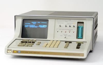 |
The HP 1611A Logic Analyzer |
The HP 1611A,
A Logic State Analyzer for Microprocessor Systems
Fortunately, the microprocessor, which generated the need for a new type of analyzer, had also provided a solution to the problems of implementing it in a form that was both convenient to use and possible to built.
The HP 1611A was introduced in 1977, with the main purpose of debugging systems that used popular microprocessors of the time. It was the first Logic State Analyzer with keyboard control, and the first Hewlett Packard instrument with a Mnemonic display.
Two paragraphs in Chuck House's LSA story give us an insight in the development of the 1611A:
"While ASM designs had proliferated, the rapid growth of microprocessors changed the rules. We built microprocessors into our entire line, the first time any test equipment vendor used microprocessors in tools to monitor microprocessors. More capabilities were added to these state analyzers - wider busses, sequential state triggering, and alternative displays, including decoded octal, hexadecimal, and microprocessor mnemonic instruction sets that replaced the "1's" and "0's" and state space maps that helped illustrate more complex state flows.
The first product out of the gate was led by Jeff Smith, an experienced sampling 'scope and pulse generator designer, who teamed with a native Colorado Springs software developer, Tom Saponas, to define and create the HP 1611A Logic State Analyzer. The HP 1611A featured 'plug-in personality modules', each tuned for individual microcode instruction sets for a specific microprocessor from one company. The first module released was for Intel's newly released 8080 microcomputer. Personality module designers included Gail Hamilton, Dave Hood and Debbie Ogden. Don Bloyer, Don Miller and Roger Molnar contributed product design skills, each of them experienced in our 'scope labs."
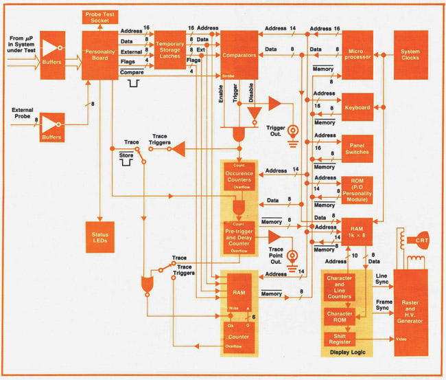 |
Simplified Block Diagram of the HP 1611A Logic State Analyzer - From the January 1977 issue of the Hewlett Packard Journal |
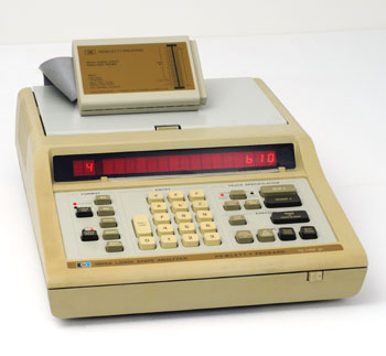 |
The HP 1602A |
The HP 1602A
Logic State Analyzer
The HP 1602A was introduced in the February, 1978 Hewlett Packard Journal.
It was an entry level, low cost, Logic State Analyzer, designed with the main guideline to be operable by a first-time user with a minimum of prior instruction. Moreover, it was programmable, making possible automatic systems for functional and production testing.
The 1602A has a 16-bit wide and 64-word deep memory operated at clock speeds to 10 MHz allowing the instrument to capture virtually any 64-word sequence in a system.
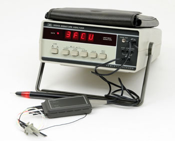 |
The HP 5004A Signature Analyzer |
The HP 5004A
Signature Analyzer
By the mid-seventies, better methods to meet the service challenge imposed by the proliferation of microprocessor based products were needed.
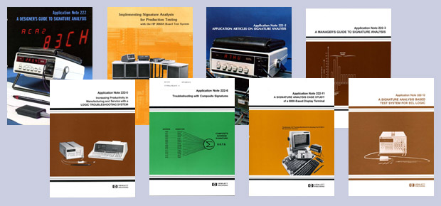
Signature Analysis is an HP-invented and patented technique which displayed a compressed, four-digit "fingerprint," of the data stream present at a node of logic circuitry. The AN 222, edited in 1977, gives a detailed description of the signature analysis concept. It is available here as a 10 Mb PDF file:
AN 222 - "A Designer's Guide to Signature Analysis"
The HP 5004A was a tool for production and service troubleshooting of complex logic circuits. It reduced the skill level necessary to troubleshoot microprocessor-based products to the component level.
This completely new, service-oriented concept took its full power during the second half of the 1970s. Its only drawback was that it required that the device to be tested by signature analysis had to be designed from the Lab-phase for signature analysis testing. But in the objective to convince engineers to opt for this technique at the design level, Hewlett Packard as usual, invested in a huge quantity of training material dedicated to the signature analysis concept. The application notes of the 222 series by themselves totalized more than 170 pages of technical documentation to help electronic designers to implement signature analysis in their products.
 |
 |
The HP 5036A Logic Lab |
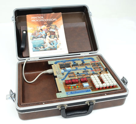
The HP 5036A Logic Lab. Another Learning Tool,
And one more time, for a lot of people, with the introduction of the microprocessor, came the need to learn these new technologies from scratch.
In this perspective, HP introduced the Model 5036A Microprocessor Lab, a well-thought-out Training Tool, which included a keyboard-controlled microcomputer in a briefcase, and a comprehensive textbook with a number of lessons and experiments.
The HP 5036A was designed to provide both the hardware and software basics and vital troubleshooting information to train new people to solve the microprocessor puzzle.
The main target of the 5036A Microprocessor Lab was the service technicians, but many units were distributed inside HP for the disposal of the sales force. Most HP field engineers in the seventies were coming from the analog world, and many of them had their electronic education at the time of the fledging transistor. Needless to say a lot of training and refresher courses were mandatory to a large number of them. Even if many other educational alternatives were available on the market of the time, the 5036A Lab was by far the best way to learn and practice microprocessor circuits. Designed by engineers directly concerned by the success of the logic instrumentation product line, it was intended to educate people who were the most motivated by this success, the field engineers in charge of their sales.
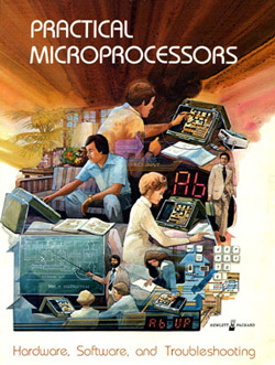 |
To help fully understand microcomputer systems, a user needed to understand both software and hardware. The 5036A course book, Practical Microprocessors, covered both areas in detail in separate chapters containing summaries, hands-on experiments and quizzes. Once these chapters were completed, the course built up to a series of troubleshooting experiments employing recommended accessory troubleshooting instruments that challenged the user and reinforced major microprocessor operating concepts.
In addition to microcomputer basics, the book contained information on the use of oscilloscopes, signature analyzers, logic analyzers, logic probes and many other topics.
We do not plan to scan and reproduce here the 450 pages of the Practical Microprocessor textbook, but for those who would like to get a foretaste of its content, the 14 pages of its introduction are available here as a 3.4 Mb PDF.
PRACTICAL MICROPROCESSORS, introduction
From Nothing to a 150 M$ Business in less than a Decade
In conclusion to this first phase of the Logic Analyzer product line, among the huge quantity of data unveiled in Chuck House's story, this short excerpt and graphic below gives a clear illustration of the success of the LSA product line at HP.
"HP's pioneering Logic Analyzer line cumulatively sold $150 million, besting our old nemesis Tektronix ($99 million) in the first seven years, through the end of 1980. Those were satisfying years, especially given the doormat status that our 'scopes always suffered." (See graphic below)
Click in this link to read the full story: "Logic State Analyzer Birthing Pains," by Chuck House
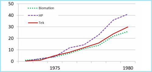 |
Logic Analyzer sales (Biomation, HP, and Tektronix) 1972-1980 |
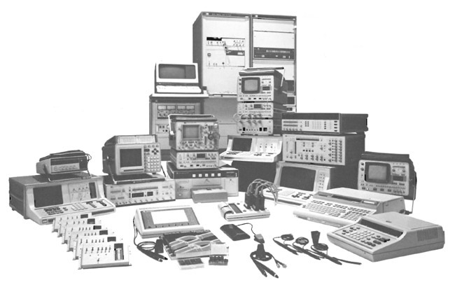 |
The HP Logic Test Family in 1979 - Photo from Measure Magazine, January 1979 |
