1960 - The First Sampling Oscilloscope
As described in the first period of this Quick Tour, one could says that oscilloscopes at HP were not an immediately successful product line. In the HP Way, making a contribution was an important concern when designing a new instrument. The 185A was the first HP oscilloscope to make a contribution to the waveform measurement limit of the time.
This was a good reason for Bill Hewlett to list this instrument in his book: "Inventions of Opportunity" edited in 1983:
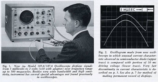
"This article describes one of the important developments by the company in the early 1960s. There was an ever-increasing demand for methods to measure high-speed waveshapes of periodic recurring signals. Conventional techniques at the time were capable of producing oscilloscopes with a top frequency range of 50 to 100 MHz. The technology described in this article permitted the development of an oscilloscope with a 500 MHz upper limit. The capabilities of this scope depended upon a very old technique almost forgotten, that of waveform sampling. Early use of waveform sampling was in the power generation field, where the waveform of an alternator could be measured by means of a movable commutator that could sample the instantaneous voltage of an alternator at various positions of the rotor. Actual measurement of this voltage was achieved with a condenser and a simple dc voltmeter. The technique had proven to be applicable to very high-speed signals, and the sampling scope described was the first practical application of this concept."
The HP Model 185A/187A Sampling Oscilloscope - Page 1 of the Jan-Mar, 1960 Hewlett Packard Journal
Courtesy of the Hewlett Packard company |
 |
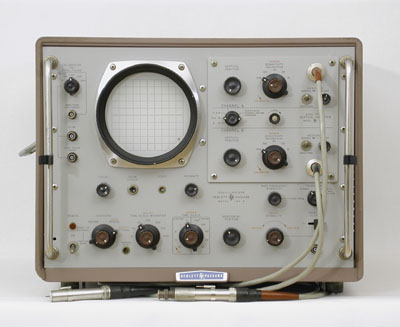 |
HP 185B - First 1 kMc Sampling Oscilloscope
|
HP 185B - The Kilomegacycle Sampling Oscilloscope
Just two years later, the HP 185B was introduced in the March 1962 issue of the Hewlett Packard Journal.
The 185B mainframe with the 187B drawer combination, extended the equivalent bandwidth of the previous model HP 185A to the Gigahertz region. Thus giving the Journal the opportunity to title its article with the nickname "The Kilomegacycle Sampling Oscilloscope".
Brief specifications of the 185B when used with the 187B Dual trace Amplifier were: DC to 1000 mc passband with a rise time of less than 0.4 nanosec. Sensitivity from 10 mv/cm to 200 mv/cm in 1, 2, 5 sequence. Input impedance 100 K shunted by 2 pf, nominal.
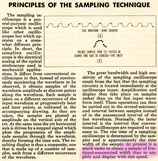
The Signal Sampling Principles - As described on Page 4 of the March, 1962 Hewlett Packard Journal
On a Technology history point of view the last sentence is particularly significant.
Courtesy of the Hewlett Packard company |
 |
The Oscilloscope Product Line Evolution Over Two Decades
Without question the oscilloscope is the instrument, which was submitted to the largest number of technology changes over two decades, 1960 to 1980. Except for the computer, no other product ever generated such a complete technology change over such a small time period. During the 1960-1980 period, more than seven different families of oscilloscope would succeed or complete each other to offer the largest choice to the various customer needs. In the order of appearance, the different family names were: 120, 130, 140, 1200, 180, 1700 and 1740.
The oscilloscope was one of the very few product lines in which HP leadership was not an easy conquest. Permanent competition against Tektronix generated one of the biggest sales and marketing activities all through the 1960-1980 periods. Fortunately this has also generated a huge quantity of documents, in the form of short catalogues, dedicated datasheets and specific application notes.
The short-form catalogues dedicated to specific families of oscilloscopes were the best source of information for a customer to make the right choice of the right product for its application. Having had the chance to save a lot of these documents from the trash, we think they could be the best tools to make a recap today.
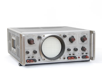 |
HP 130C Oscilloscope
|
The 130 Series
The 130 series of oscilloscopes had many versions during the beginning of the 60s. The 130 series were not designed for high performance but rather to offer various solutions where and when an oscilloscope display had to be integrated into an electronic test system.
They are general-purpose oscilloscopes designed to fit the needs of the industry in the low frequency, audio and vibration analysis.
Inside the HP 130 series, the 132A was the only HP Dual-Beam Cathode Ray Tube oscilloscope ever produced.
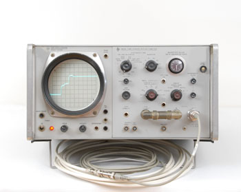 |
HP 140A Mainframe
with 1415A Time Domain Reflectometry Drawer
|
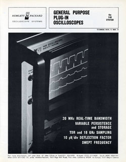
The 140 Series,
and the
1415A, First TDR
The first oscilloscope of the 140 series was the HP 140A mainframe, which appeared in the 1963 catalog.
The choice of the Mainframe-Drawer solution probably came from the competitive challenge with Tektronix. None of the many drawers developed for general purpose oscilloscopic measurements would be a significant technology advance compared to the oscilloscope market of the time. But HP quickly included many new products in the 140 series counting on their technology leadership... Sampling, TDR and Spectrum Analysis. The result would be that by the end of the 60s, a complete product line including a scope with 20 picosecond rise time and spectrum analyzers up to 18 GHz.
The birth of the Time Domain Reflectometry at HP came also with the 1415A drawer in the 140A mainframe, introduced in the September 1963 of the Hewlett Packard Journal:
"High-resolution time-domain reflectometry measurements are made practical by the Model 1415A TDR plug-in for the Model 140A Oscilloscope. Time domain reflectometry is a relatively new impedance-measurement technique which gives accurate, quantitative, easy-to-interpret information about mismatching, loss, reflection coefficients, and other parameters of electrical transmission systems.
The technique, analogous to the pulse-reflection principle used in radar, has been used for some time as a means of locating faults on long electric power and telephone transmission systems. The extremely fine resolution available in the Model 1415A, however, enables application of the pulse-reflection technique to systems with much smaller dimensions. The Model 1415A plug-in with the Model 140A Oscilloscope displays cable discontinuities separated by only fractions of an inch."
For an in- depth understanding of Time Domain Reflectometry two important Application Notes were published. The AN-62 printed in 1964 was dedicated to the basis of "Time Domain Reflectometry", and the AN-67 printed in May 1968 was titled "Cable Testing with Time Domain Reflectometry". Copy of the originals of these two application notes have been added to the AN Page of this web site at the same time this Oscilloscope chapter was inserted.
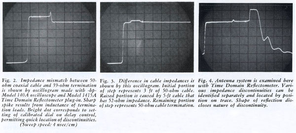
Practical TDR Measurements with the HP 1415A - From the September, 1963 Hewlett Packard Journal
Courtesy of the Hewlett Packard company |
 |
The 140 Series
At the beginning of the 70s, with its 5 different mainframes and 22 high-performance plug-ins, the 140 oscilloscope system provided the largest measurement spectrum to choose from: Wideband, Sampling, High-Sensitivity, Time Domain Reflectometry and Swept Frequency.
The performance of the various configurations would be progressively supplanted by the next generation of oscilloscopes growing all through the 1970s. But many of the most popular configurations, associating a 141T mainframe and 855X spectrum analyzer drawers are still alive today, and they offer low cost access to high performance Audio and Microwave spectrum analysis to many enthusiasts.
The link below gives access to a copy of the 30 page original short-form catalog. PDF format (13.1 Mb)
HP 140 Series Technical Data. March 1971.
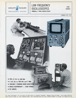
The 1200 Series
The 130 series oscilloscopes were replaced progressively by the 1200 series by the end of the 60s. The main improvement was the full-transistorized design providing reliable, low maintenance operation with less frequent calibration requirements.
The 1200 series oscilloscopes are low frequency, all solid-state instruments matching the needs of production line testing, system applications and classroom or laboratory instruction.
Every oscilloscope of the 1200 series uses an HP rectangular CRT with parallax-free internal graticule.
The link below gives access to a copy of the 8 page original short-form catalog. PDF format (4 Mb)
HP 1200 Series Technical Data. February 1972.
 |
HP 1200A
|
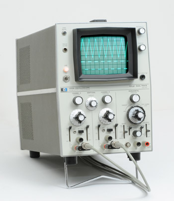
The HP 1200A
All solid-state, low frequency 1200-series oscilloscopes offered advanced performance with operating features previously available only on much wider bandwidth, and more expensive instruments.
The HP 1200A was the basic instrument in the 1200 series. It was a dual trace oscilloscope with a 500 kHz bandwidth, and a very high sensitivity of 100 microvolts per division on the lowest of its 17 input ranges.
Other characteristics rarely found on oscilloscope of that era were a very low drift, and a very high common-mode rejection ratio of 100 dB on the lowest deflection factor of 0.1 mV/div, over a DC to 10 kHz frequency range.
The 1200A, and five other members of the 1200 series were introduced at the same time in the 1969 HP general catalog.
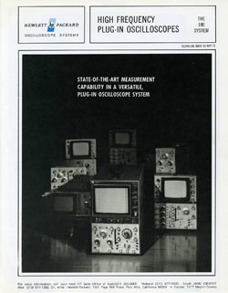
The HP 180 Family
The very first members of the HP 180 family were the 180A mainframe, the 1801A dual-channel 50 MHz amplifier and the 1820-21A time base. They were presented for the first time at the Hewlett-Packard WESCON, Hollywood Park, in August 1966.
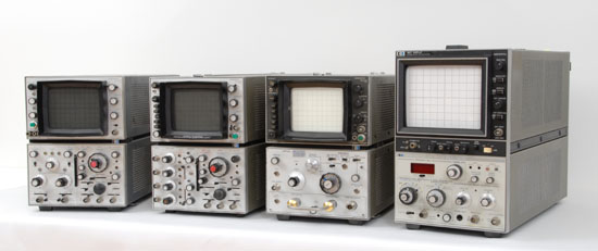
HP 180 Oscilloscope Family Shown with various drawers
Mainframes are (Left to Right) - 180A Basic, 50 MHz - 181A Analog Storage - 181T, Variable Persistance 100 MHz
182T Large Screen Spectrum Analyser Display |
 |
The 180 Series, Short-Form Catalog
The salesman's message to his customers for the HP 180 oscilloscope family was the following:
"Whatever you're looking for in a general-purpose lab scope, you can find it in the 180 System. A choice of mainframes, plug-ins, and accessories lets you "custom design" the scope system that best suits your needs, selecting bandwidth range, screen size, writing speed, sweep, sampling, TDR, and storage capabilities, as your requirements demand. And because all elements of the 180 System are fully compatible with each other, you can expand your scope's capabilities as your needs change."
The link below gives access to a copy of the 16 page original short-form catalog. PDF format (6.8 Mb)
HP 180 Series Technical Data. October 1971.
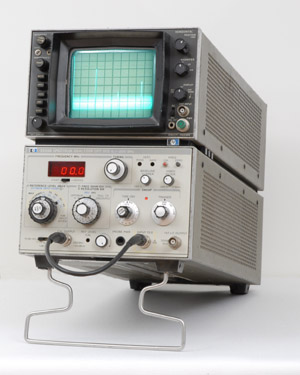 |
HP 181T Mainframe
with 8558B Spectrum Analyzer Drawer
|
The HP 8558A Spectrum Analyzer
The HP 8558B Spectrum Analyzer is certainly the largest diffused instrument of the 180 series. It is still today a very low cost, good performance solution, frequently found in general purpose RF workshops.
The HP 8558B Spectrum Analyzer is a fully calibrated spectrum analyzer designed for simple operation. It is a plug-in which fits into any HP 180 Series oscilloscope mainframe.
The analyzer has a frequency range from 100 kHz to 1500 MHz and a digital LED readout for more accurate frequency measurements. Absolute Amplitude calibration enables accurate voltage and power measurements to be made.
Through the use of coupled controls, the instrument can be made to operate using only three knobs. A simple three-knob operation means the inexperienced user needs very little training.
Reduced cost and portability opened the 8558B to a very large diffusion as a bench and on site service instrument, mainly in the telecommunication and CATV applications.
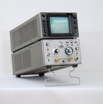 |
HP 1818A TDR Drawer in 181T Mainframe
|
The HP 1818A TDR
The 1818A was the lastest evolution and the most sophisticated Time Domain Reflectometer of the 180 series.
The 180X/1818A combination is a completely integrated wide band system for testing transmission lines, strip lines, cables, connectors, and many other devices in high frequency systems. The front panel controls provide accurate direct distance calibrated displays of up to 300 meters. Thus allowing to quickly determine the magnitude and nature of each resistive or reactive discontinuity in coaxial components such as attenuators, cables, connectors, and delay lines in microwave or pulse circuits. Faults such as shorts, opens, loose connectors, defective tap offs, splices, and mismatches can be located and identify with measurement resolution as close as 2.54 cm.
The 1700, Portable Family
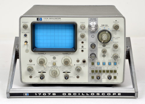
The HP 1700 Series Oscilloscopes are lightweight, battery operated, portable instruments designed for both lab and field service applications. All models are dual channel and have either 35 or 75 MHz bandwidths. Models with a main time base only, or with both main and delayed time bases can be chosen from. The 1700 series also includes two models with variable persistence and storage CRT's.
| The HP 1707B |
 |
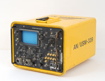 |
AN/USM-339 Ruggedized version of the 1700B
|
The 1700, Ruggedized
The device shown in the pictures on the right, and below, is certainly not the most representative of the 1700 series of oscilloscopes. But it is nevertheless an interesting and symbolic example of the HP special production responding to military requirements.
The AN/USM-339 is the ruggedized version of the HP 1700B. It is a lightweight, portable oscilloscope specifically designed for the rugged requirements of military operations. Operation in dusty environments cause no problem due to the lack of ventilating holes, which allows the 1700E to pass the Dust Test of Method 510. Procedure I of MIL-STD-810. In fact, the 1700E can operate in chemical plants, refineries or many other locations where corrosive or adverse atmospheres may be present. The environmentally designed construction makes it very difficult for any contaminants to get inside the oscilloscope.
This unique ability to operate in an adverse environment is made possible by the extremely low power consumption of the standard 1700 Series oscilloscopes. When operating on ac line power, these oscilloscopes consume less than 25 watts and when operating on dc line or optional internal battery pack, power dissipation is only 18 watts. This means that no vent holes are required and the oscilloscope can be tightly sealed with little concern for internal heat buildup. The majority of the internal components are designed to operate at only 10 to 20 per cent of their maximum rated power which assures high reliability. The lack of ventilation holes also increases measurement reliability by reducing short term dc drift caused by transient ambient temperature changes.
Nobody quite knows which customers are going to want an underwater oscilloscope,
or what they might do with one, but the fact is that HP has developed just such a critter.
It's the 1700E environment-proof scope that's being introduced to the world at this
month's IEEE show in New York. The 1700E came about because of specifications
that called for a ruggedized instrument able to take-among other things-a lot of salt water splashing.
The Colorado Springs' designers turned to the 1700 series portable scopes because of their low power
consumption and low heat dissipation requiring no vent holes.
Then they added a system of
gaskets and sealants. This made the instrument completely waterproof even with the front-panel
cover removed. However, anyone planning an undewater test had better bring along an anchor,
the 35-pound 1700E also floats.
|
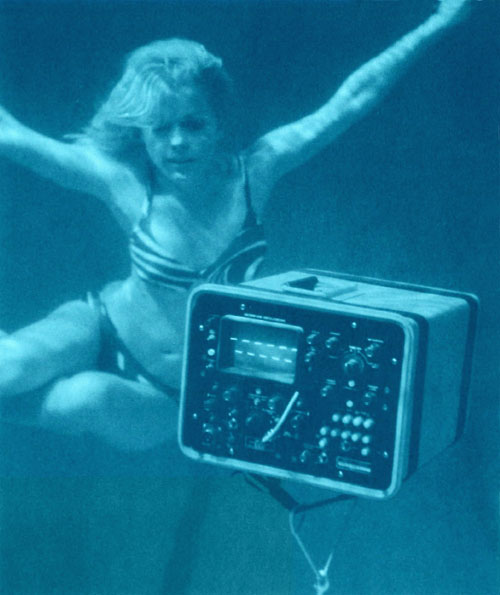 |
From Measure Magazine, March 1972 - Courtesy of the Hewlett Packard Company
|
The Model 1700 Portable, Short-Form Catalog
The other members of the 1700 portable family have a slightly less warrior look and feel, but they respond to the same criteria of performance and power consumption.
The link below gives access to a copy of the 12 page original short-form catalog. PDF format (4 Mb)
HP 1700 Series Technical Data. December 1971.
The HP 1740 Family
The end of 1975 saw the birth of the general-purpose HP 1740A dual-trace, 100 MHz portable oscilloscope and the 1740 product line developed all through the second half of the seventies. Following the many technological evolutions of this period, new models were added each time the state of the art permitted a serious performance improvement. A passband raised to 275 MHz with the 1725A in 1978, a fast variable persistence storage CRT with the 1744A in 1979. But above all, the 1743A integrated a crystal controlled time base allowing high resolution delta time measurement. This could be considered as the first sign of the slow transition from analog to digital waveform measurement. The next step of this transition would be a revolution, with the introduction of the HP 1980A/B in 1982.
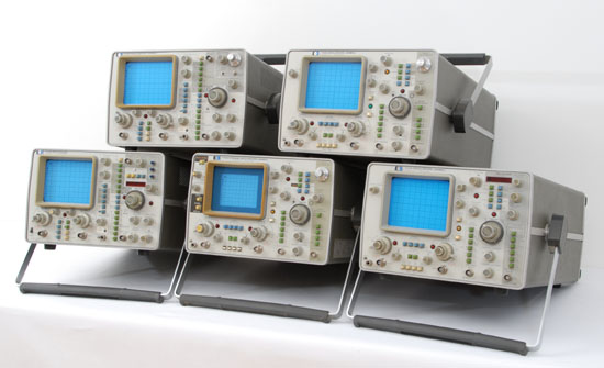
HP 174X Family
(Top Row) left : 1715A - right : 1740A
(Bottom Row) left : 1722B - center: 1744A - right: 1743A |
 |
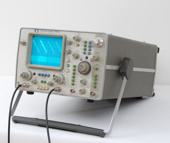 |
HP 1740A Oscilloscope
|
The HP 1740A
The first member of the 1740 series was introduced in the 1976 catalog. It was a dual trace, DC to 100 MHz bandwidth oscilloscope which could display the sweep trigger waveform as a third trace simultaneously.
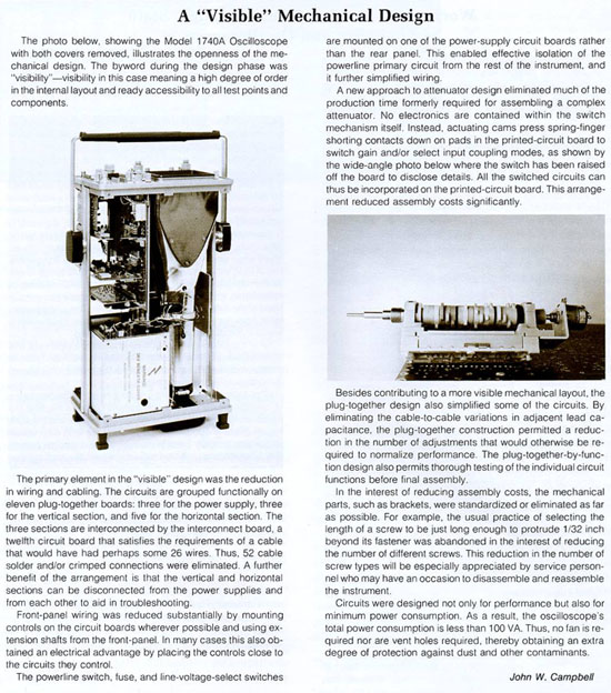
Although a completely new mechanical design was developed for the 1740 series, (see article below,) it was decided to retain some elements of earlier designs when they were of proven performance and reliability. One of these was the cathode-ray tube. The CRT used in the 180 series oscilloscopes had been improved over the years and in the course of building 40,000 or so. By the way it was re-used for this first unit of the 1740 family.
Another technique retained from earlier designs was the trigger recognition circuits. For both the main and delayed sweeps, the new scope uses the same HP monolithic integrated circuits as the 275-MHz Model 1720A Oscilloscope. They provide stable triggering on signals above 100 MHz but require an amplitude equivalent to only 1 cm of deflection at 100 MHz to do so.
Mechanical Design of the 1740 Oscilloscope Family - Page 6 of the December, 1975 Hewlett Packard Journal
Courtesy of the Hewlett Packard company |
 |
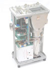
Animation Display: Interior Panoramic View of the HP 1745A
Animation |
 |
|
 |
HP 1727A Oscilloscope
|
The HP 1727A,
Fast-Writing Storage Oscilloscope
Combining extremely fast writing rate (2000 cm/µs) with high-bandwidth (275 MHz), the HP Model 1727A Oscilloscope was the most sophisticated storage oscilloscope of the 1700 series.
The 1727A uses Hewlett-Packard's expansion storage technology which combines a precision storage mesh with an electronic lens system that magnifies and projects the stored image on the viewing screen.
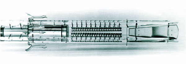
The 1727A uses a transmission-line deflection plate structure (see picture below) that appears to the vertical output amplifier as a resistive load rather than a capacitive load. This results in a much higher bandwidth than is possible with conventional deflection plates.
Inside View of the HP 1727A CRT Showing the Transmission Line Vertical Deflection Plate Structure
From the April, 1982 Hewlett Packard Journal
Courtesy of the Hewlett Packard company |
 |
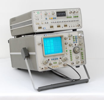 |
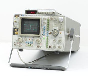
Combination of the HP 1740A Oscilloscope
and HP 1607A Logic State Analyzer
in a Package Know as Model 1740S
|
The HP 1740S,
Signs of Things to Come...
The 1601L, logic state analyzer was the first attempt made by HP to extend the field of use of the oscilloscope to the logic circuitry analysis. It was a drawer fitting in a series 180 mainframe, introduced in the January 1974, Hewlett Packard Journal.
The HP 1607A, presented at the same time as the first oscilloscope of the new 1740 family, was a clear sign that in 1976, the classic oscilloscope needed to add something new to its fundamental vocation of Time Domain Analysis: The Data Domain.
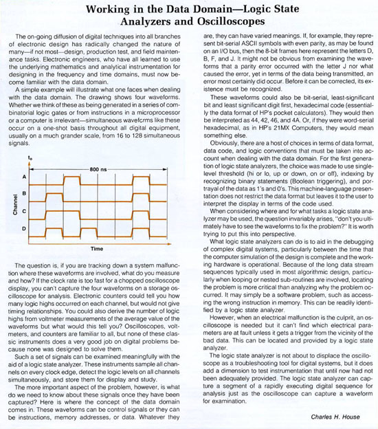
The basis of these new Data Domain measurements were explained in detail by Chuck House in an article published in the December, 1975 issue of the Hewlett Packard Journal. (Reproduced below.)
This early and hybrid solution to the growing need of specific logic circuit measurement, would quickly let the place to a new category of instrument, fully dedicated to this task: The Logic Analyzer. As you could see on the selector page that brought you here, a chapter dedicated to Logic Analyzer is planed on this web site. Like the many other to come... It's under construction... Stay tuned ;-)
A listing of the actual collection of Logic Analyzers is visible here: Logic Analyzers
Chuck House Analysis of the growing need of a Data Domain Analyzer in the December, 1975 Hewlett Packard Journal
Courtesy of the Hewlett Packard company |
 |