Evolution of the Pulse Generator Product Line during the 1960s & 1970s
Early pulse generators were designed to fit the very simple needs of labs during the 1940s and 1950s. Their usage was limited to the simulation of electric phenomena, to the triggering of oscilloscopes, or to test amplifier rise time. Evolution from these simple original requirements was spurred by the multiplication of new technologies requiring more and more accurate and complex pulse signal generation. Radar, TV, and Cable TV, were the first applications, during the early sixties, to enlarge the pulse generator product line. These fast growing markets encouraged HP to provide a wide range of instrument capabilities, letting the customer choose a pulse generator exactly tailored to his testing needs. Then, by the mid-sixties, another completely new market appeared... the computer market. It required pulse generators with performance specifically dedicated to computer technology. This new kind of pulse generator quickly adapted to the specific task of logic circuit stimulation. During the seventies, this new category of pulse generator was born: The binary word generator. Word generators are used to produce the complex waveforms necessary for logic circuit testing, telecommunications system development, and for interface simulation.
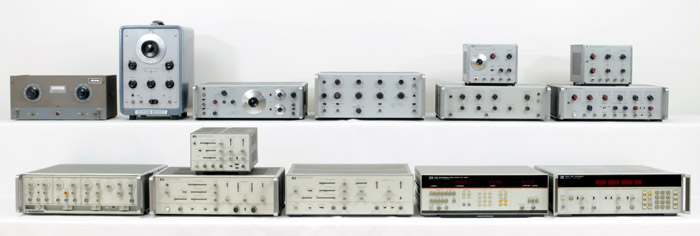 |
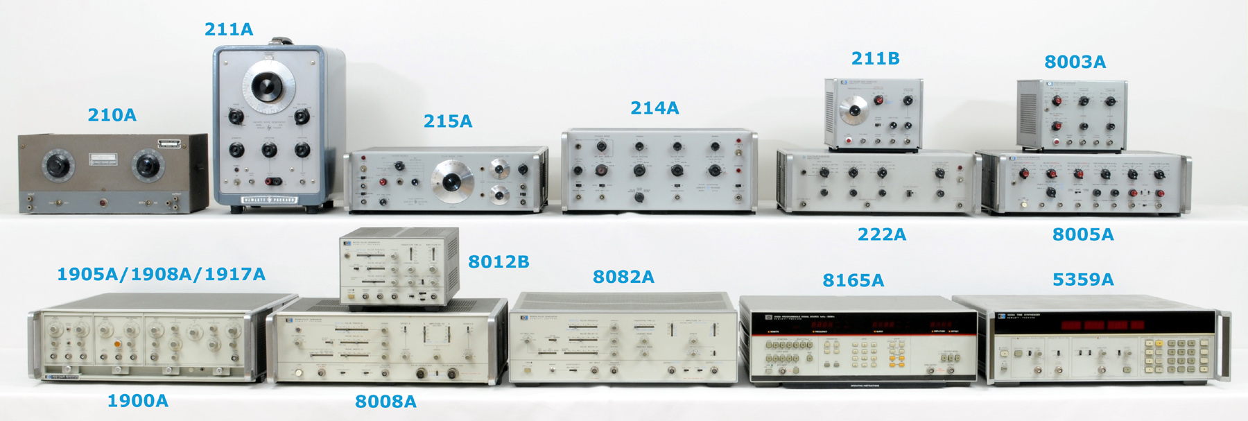
Various HP Pulse Generators, from the early 1940s to the ending 1970s
Click-in Picture for Detail |
 |
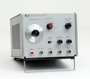
The HP 215A Pulse Generator
|
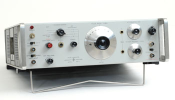
The HP 215A
The HP 215A was Introduced in a 1962 short-form catalog, as "Today's only pulse generator combining 1 ns rise and decay time with convenience of calibrated, continuous control over pulse length and delay."
By the beginning 1960s, such performance was a new concern, mainly required by the fledging semiconductor consumer market. Measuring the switching and recovery time of diodes, transistors, logic circuits and thin-film memory units was becoming a major concern.
Fast circuit investigations were further assisted by this versatile new pulse generator which provided pulses as short as 1 nanosecond ( 10-E9 second).
The 215A, when combined with the "Kilomegacycle Sampling Oscilloscope," introduced in March 1962, comprised a complete fast-circuit testing system for the usual stimulus-response type of tests.
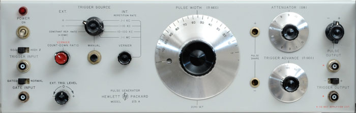 |
| Detail of the HP 215A Front Panel |
Conventional techniques for generating pulses with nanosecond rise times were not flexible enough for a general purpose pulse generator in 1962. The main difficulty lay in maintaining constant pulse height, along with prescribed rise and fall times, while pulse width is varied. The problem was solved in the Model 215A by deriving a pulse from two very fast current steps, one positive and one negative, generated in separate channels. The fast rise times of these steps, and hence of the pulse derived therefrom, resulted from the use of step-recovery diodes as pulse "sharpeners," as shown on the block diagram below.
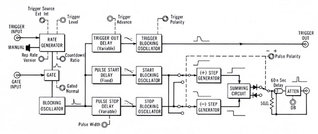 |
| Basic circuit arrangement of the HP Model 215 A Pulse Generator. |
 |
HP 214A
|
The HP 214A
The HP 214A, High-Power, Fast-Rise, pulse generator was introduced in the 1963 general catalog.
Fast risetime pulses with appreciable power at high repetition rates were necessary to respond to a large demand in a growing number of applications by the beginning 1960s. The testing of magnetic cores, ferrite modulators, high speed relays, and high power semiconductor devices represent some of the uses for pulses of considerable current. Pulses with ample voltage are useful for testing power amplifiers, wideband modulators, and the ionization times of neon bulbs, thyratrons, and other gaseous devices.
To meet this demand for high power pulses the Model 214A pulse generator has been designed to supply up to 200 watts in its output pulse, at repetition rates up to 1 Mc. Maximum pulse amplitude into a 50 Ω load is 100 volts, four times the power previously available in a general purpose pulse generator. Maximum pulse current into a short circuit is 2 amperes. Pulse rise and fall times at 100 volts are typically less than 15 nsec and are reduced to less than 13 nanoseconds for pulse amplitudes of 50 volts (into 50 Ω) or less.
The Model 214 A Pulse Generator, supplying up to 2 amperes of pulsed forward current, had a great contribution for the study of light spectra radiated by electroluminescent diodes which were in their very early development stage by the beginning 1960s.

|
Use your scrollwheel to zoom in/out
--
Click and drag to view other parts of the image when zoomed |
|
|
|
Top-Inside View of the 214A Pulse Generator
|
 |
The HP 211B
|
The HP 211B,
Expending the pulse generator product line to the low cost, general purpose area, the HP 211B was introduced in the 1967 general catalog.
The Model 211B is a compact, fully transistorized Square Wave generator for general purpose laboratory and production line applications. It provides frequency coverage from 1 Hertz to 10 MHz in seven decade ranges with a linearly calibrated dial for continuous adjustment on all positions.
Square waves or pulses?
The fundamental difference between pulse and square wave generators concerns the signal duty cycle. Square wave generators have equal "ON" and "OFF" periods, this equality being retained as the repetition frequency is varied. The duration of a pulse generator "ON" period, on the other hand, is independent of pulse repetition rate. The duty cycle of a pulse generator can be made quite low so that these instruments are generally able to supply more power during the "ON" period than square wave generators.
Short pulses reduce power dissipation in the component or system under test. For example, measurements of transistor gain are made with pulses short enough to prevent junction heating and the consequent effect of heat on transistor gain.
Square wave generators are used where the low-frequency characteristics of a system are important, such as in the testing of audio systems. Square waves also are preferable to short pulses if the transient response of a system requires some time to settle down.
 |
HP 8406A
|
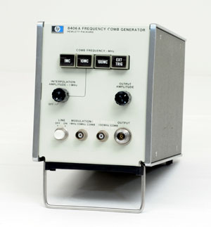
The HP 8406A
Comb Generator
Even if it is not obvious to place the 8406A in the pulse generator category of instruments, it is still mainly a generator of pulses. It appeared for the first time in the 1967 catalog, in which it was presented as a convenient and accurate frequency calibration accessory for the HP Model 851A/8551A (broadband spectrum analyzer).
The 8406A comb generator has three internal crystal-controlled oscillators at frequencies of 1, 10, and 100 MHz, and a step recovery diode that shapes the oscillator outputs into extremely narrow pulses less than 100 picoseconds wide. The result is the generation of a comb of marker frequencies with useful amplitude from 1 MHz to beyond 5 GHz.
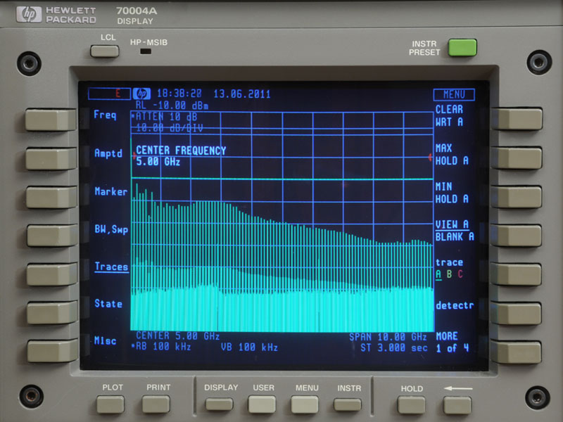
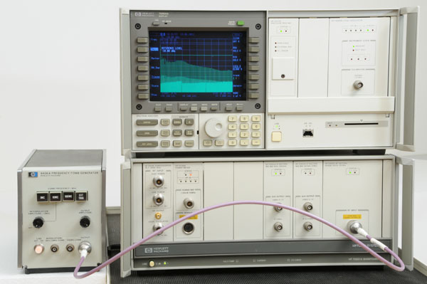
Although not really useful with a synthesized spectrum analyzer like the one shown below, the purpose of this picture is to show the comb of pulses output from a 8406A in a single 10 GHz span. Precisely separated markers at 1, 10, or 100 MHz was the only way to verify the horizontal frequency calibration of an analog spectrum analyzer. The HP 8406A was a precious, low-cost tool, for the engineer using an 8551 in the 1960s, or a 8558 in the 1970s. And even more precious to the service technicians who have to adjust the sawtooth shaping circuit of such an analyzer.
HP 8406A Comb Generator
Click-in Picture for a High Resolution View of the Spectrum Analyzer Display |
 |
 |
The HP 8003A
|
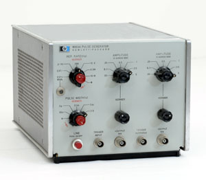
The HP 8003A,
Introduced in 1968, the HP 8003A was the first HP pulse generator offering an option for remote programming of the repetition rate, pulse width, and amplitude of the output signal. Long before the birth of a standardized computer interface, Option 01 of the 8003A permitted to program these major parameters by simple contact closure to ground.
In 1968, two years after the introduction of the Model 2116, the first HP computer integrated more and more instruments into automated systems. However, just 5 years before the birth of the HP-IB, this first generation computer required the addition of one dedicated interface card for each instrument controlled by the system. The last stage in most of these interfaces provided a contact closure through the emitter-collector junction of an output transistor.
Main specifications of the 8003A were 5 ns rise time, 10 MHz repetition rate, and simultaneous positive and negative output at a maximum level of 5 Volts across 50 Ω.
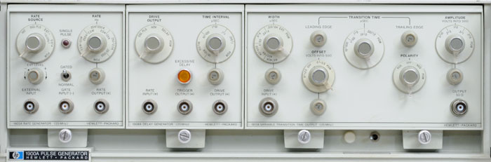 |
The HP Memory Collection HP 1900A Pulse System Loaded with, from left to right,
1905A Rate Generator, 1908A Delay Generator, and 1917A Variable Transition Time Output |
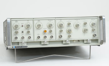 |
The HP 1900A
|
The HP 1900A,
The 1900A modular pulse generator mainframe, introduced in 1969, was another step towards the objective of building pulse systems tailored to fit exact requirements, from general laboratory use to fully automated production test systems.
All solid-state, the 1900A system mainframe contains only power supplies, with optional programming wiring added if desired. The plug-in compartment accepts any combination of a choice of half-size or quarter-size plug-ins.
Three plug-ins were available at the first introduction in 1968. The 1905A Rate Generator was the clock source providing output triggers at repetition rates from 25 Hz to 25 MHz. Pulses from the 1905A, up to 25 MHz in frequency, may be advanced or delayed with the Model 1908A Delay Generator in a range from 15 ns to 10 ms. And the Model 1915A Variable Transition Time Output Amplifier provided high-power, variable risetime and falltime output pulses.
Later in 1969, new plug-ins were introduced, and they were described in the March 1969 issue of the Hewlett Packard Journal. Among them, the Model 1925A, gave the 1900A system the ability to generate "WORDS" for digital testing, thus making the Model 1900A the first HP instrument to introduce the concept of Logic Word Generation. As we know today, an innovation which would have a huge success in the following years.
 |
HP 8012B
|
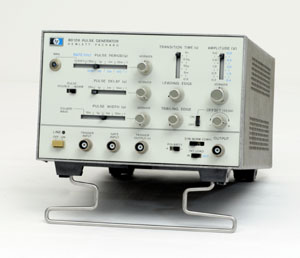
The HP 8012B
The expansion of the Pulse Generator product line during the 1970s was mainly spurred by the need for instruments capable of testing high-speed logic circuits such as ECL and Schottky-TTL. An exhaustive listing of the Pulse Generator product Line available at HP, by the end of the seventies, is available in the PDF copy of a short-form catalog dedicated to Pulse Generators, reproduced below.
The HP 8012B shown on the right is a low-cost product entry in the very large portfolio of pulse generators produced by the HP Gmbh Boeblingen Divison during the 1970s.
The 8012B is a general purpose solution to almost all digital testing problems of that era. It provides variable transition times down to 5 ns ideal for testing TTL integrated circuits. The repetition rate can be adjusted from 1 Hz to 50 MHz, and the output circuitry can deliver up to ± 10 V amplitude into a 50 Ω load. The 8012B has also a double-pulse, and a square wave mode of operation.
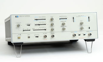 |
The HP 8082A
|
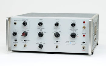
The HP 8082A,
Another example of the HP Boeblingen Division productions in the 1970s, the Model 8082A Pulse Generator gives control of transition times over a range of 1 ns to 5 ms, and pulse repetition rates as high as 250 MHz. Two outputs are provided, with one as the complement of the other.
Developing circuits that would make transition times controllable down to 1 ns without causing excessive ringing or overshoot turned out to be the most challenging part of the project, and required microcircuit techniques.
Another concern, always in mind of the designers at HP, was the instrument's ease of use, mainly defined by the arrangement of the various controls on its front panel. For good reason, the aircraft industry had pioneered the design of control panels that allowed pilots to read at a glance and readjust almost by instinct. In fact, in other areas of industry they were still called "aircraft controls." The controls on most of the pulse generator products out of HP GmbH at Boeblingen borrowed from this concept, employing horizontal slot controls where horizontal characteristics of waveform signals are involved, and vertical slots where features such as amplitude are defined. As the photograph of the 8082A pulse generator shows below, "dial" knobs are still used, but chiefly for fine tuning. According to Joern Kos, engineering manager of pulse generators, the GmbH engineers and designers were among the first to make extensive use of the aircraft-switch concept for electronic instruments.
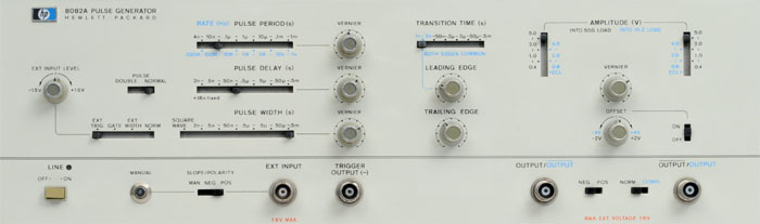 |
To speed operator familiarization, the slide switches concerned with time functions are arranged horizontally
while those concerned with pulse amplitude are arranged vertically. |
 |
Cover of a Pulse Generators Catalog of the 1970s
Courtesy of the Hewlett-Packard Company
|
A 1970s Pulse Generators
Dedicated Catalog
An exhaustive listing of the Pulse Generator product Line available at HP, by the end of the seventies, can be found in this catalog. Its contents recap all the instruments and accessories available for the generation of pulses and logical words available by the end of the 1970s.
Pulse Generators Catalog ( PDF, 4.35 Mb )
 |
HP 5359A
|
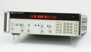
The HP 5359A
Difficult to classify, the 5359A could either be listed in the time frequency measuring instrument category, or in the synthesizer category. However, it is primarily a generator of pulses. At its introduction in 1978, Hewlett Packard chose to list it in the Electronic Counters chapter of the general catalog.
During the second half of the 1970s, newly designed instruments would integrate microprocessors, and the pulse generator product line was no exception. The microprocessor's contribution to improved performance was just in the obvious area of accurate signal generation, but to a greater extent in allowing remote control of every instrument parameter through the use of the Hewlett Packard Interface Bus (HP-IB). Since 1975, most of the characteristics of this instrument's computer communication interface, which were originally defined by HP, have been standardized by the IEEE, under the standard number IEEE-488.
With all these new technologies integrated, the 5359A was the first of a new line of pulse generators with unequaled accuracy and ultra-low pulse jitter. It would be used intensively in the construction of large test systems for the calibration of Radar, Loran, DME and Tacan Systems. Other applications were precise generation of delayed sweeps in oscilloscopes, and extremely accurate "time positioning" control of external gates on frequency counters.
The main specifications of the HP 5359A are: Repetition rate 10 MHz max. Digital delays from 0 to 160 ms in 50 ps or greater steps. Overall accuracy ± 1 ns ± time base error, and pulse jitter less than 100 ps. The output amplitude is specified at ± 0.5 to ± 5.0 Volts into a 50 Ω load with a 50 Ω source impedance.
Late 1970s, Data & Word Generators
The last evolution of the pulse generator, and first generation of data and word generators began to develop by the end of the seventies. The need for a specialized model of pulse generator was born at the same time as logic circuitry analysis born.
In contrast to a pulse generator, which normally provides continuous streams of pulses, a word generator produces digital waveforms with bit content programmed by the user. Digital information is normally encoded such that a high level or pulse represents a logical one and a low level or lack of a pulse represents a logical zero. Thus the user may determine his digital word to be 11100110 and program his word generator to produce 3 pulses followed by 2 spaces, then 2 pulses and finally a single space. Word generation may be serial, in which data is produced on only a single channel, or parallel, in which many channels of information are simultaneously produced. A repetition rate generator (clock generator) and output amplifier are normally also included to produce a self-contained unit fully capable of delivering data to a device under test.
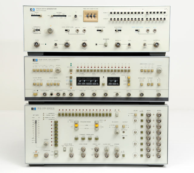
One example in each of the three categories of word, data, and pseudo-random binary sequence (PRBS) generators, are shown in the picture below:
Top: The 3760A has been specifically designed for communications applications and provides variable length PRBS and WORD patterns at repetition rates to 150 Mb per second.
Middle: The 8018A, 50 Mbit/s serial data generator containing 2048 bits of serial memory which can be delivered as a single channel or as 2 channels of 1024 bits each. Pattern length can be anything from 3 to 2048 bits, and the data stream can be divided into serial words for testing systems that are byte, character or word oriented.
Bottom: The 8016A is a 50 MHz, 8 channel word generator which can supply all of the signals necessary for testing complex MSI and LSI integrated circuits.
Collection of Data & Word Generators - from Top to Bottom:
HP 3762A Data Generator - HP 8018A Serial Data Generator - 8016A Word Generator |
 |