Testing Components in the Early Fifties
Searching through the oldest HP published literature, the very first occurence of an article dedicated to the measurement of electronic components can be found in the July 1952 issue of the Hewlett Packard Journal. But strangely, the article doesn't introduce a specific instrument to do the job.
The article is entitled: "A Novel Impedance-Measuring System Using Standard HP Instruments." It describes the basic principle, that is, when an impedance is fed from a constant-current source, the voltage across the impedance is a function of the magnitude of the impedance. This basic relation would permit using a combination of two standard instruments of the time (but why not today's equivalents) to measure extremely wide ranges of coils and capacitors as well as moderate ranges of resistors and impedances.
In fact, this article is a very good example of "Back to Basis" writing, dedicated to the fundamentals of discrete component measurements, and furthermore it included tables and monographs still usefull today in the electronic workshop.
PDF file (820 Ko) of the four page, July 1952 Hewlett Packard Journal is available here.
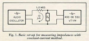 |
from the July 1952, Hewlett Packard Journal
Courtesy of the Hewlett Packard company |
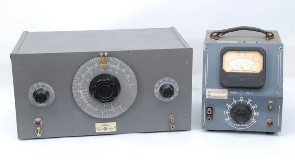 |
One possible test bench suggested by the July 1952, Hewlett Packard Journal:
A 202D Audio Oscillator and 400A Electronic Voltmeter |
1959, Hewlett Packard Boonton Division
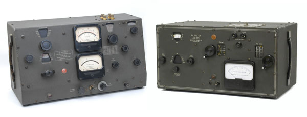
The first instruments actually designed to test component characteristics were brought to HP by the acquisition of the Boonton Radio Company (BRC) in 1959. BRC was a well respected RF instrumentation company having a lot of well designed RF instruments in its catalog. The 260A Q Meter and the 250A RX Meter, shown below, were two of them.
 |
|
Boonton 260A Q Meter left and 250A RX Meter right |
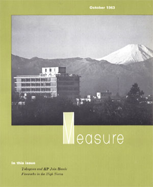 |
October 1963 MEASURE's cover
shows part of Yokogawa Electric Works
with magnificent Fujiyama in the background.
Courtesy of Hewlett-Packard Company
|
1963, Yokogawa-Hewlett-Packard
On August 14, Hewlett-Packard announced that the Japanese government had approved the corporation's agreement with the Yokogawa Electric Works, Ltd., of Tokyo to form a jointly owned company in Japan. The new company, featured in the October 1963 issue of MEASURE Magazine, would be known as Yokogawa-Hewlett-Packard, Ltd.
The 3,000 people who made up Yokogawa Electric Works manufactured literally hundreds of products, including laboratory standards instruments, chart recorders, voltmeters, cycle counters, synchroscopes, instrument transformers, DC galvanometers, circuit testers, Q-meters, oscillographs, amplifiers, and attenuators, to name just a few.
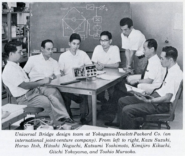
The first activity of the new joint-venture company was to add to the YEW catalog some instruments from the HP production. YHP's local version of Model 606A and 608C/D signal generators, or Model 428B clip-on milliameter are some examples of this first production. Then in 1966, the 4260A, first Yokogawa designed instrument was included in the Hewlett Packard catalog. The 4260A, semi-automatic tuning Universal Bridge would be the first of a large product line to be continued. The Component-Test products would become eventually in the following years, the most important contribution of YHP to the Hewlett Packard instrument group.
 |
|
From the September 1966 edition of the Hewlett Packard Journal - Courtesy of Hewlett-Packard Company |
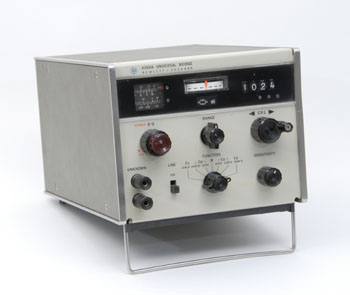 |
The 4260A Universal Bridge
First Yokogawa-Hewlett-Packard Instrument
|
The Yokogawa-Hewlett-Packard
First product: the 4260A
Universal Bridge
The 4260A was introduced in the 1966 catalog and described in the September 1966 issue of the Hewlett Packard Journal as a New Universal Impedance Bridge with simplified, semi-automatic tuning.
The 4260A has (mechanical) digital read-out, automatic decimal placement, non-ambiguous range indication and other features that simplify measurement of resistance, capacitance, inductance, Q, and loss factor.
The instrument includes five different bridge circuits selected by a FUNCTION switch which graphicaly display the wiring of the measurement circuitry in-use. The bridge measures resistance values from 10 milliohms to 10 megohms, inductance from 1 microhenry to 1000 henry, and capacitance from 1 pF to 1000 µF. It has seven ranges each for C, R, and L measurements. It achieves an accuracy of +/- 1% throughout the major portion of its range and at least 2% accuracy for the full range. The driving oscillator within the bridge operates at 1 kHz.
Animation Display: Interior Panoramic View of the HP 4260A
Animation |
 |
|
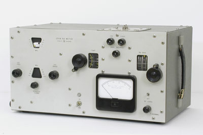 |
HP 250B RX Meter
|
The HP250B - 1968
In 1968, the original Boonton Radio 250A RX Meter was updated and re-styled to the current HP instrument look, feel, and case color. The only electronic circuit upgrade was a transistorized IF amplifier in place of the vacuum tube version of the original 250A.
Having almost no competition from any other electronic instrumentation company, the 250B would stay in the HP general catalog up to the end of the seventies with a very worthy score, close to 30 years, product life !
The 250B RX Meter measures two-terminal RF impedance in terms of equivalent parallel resistance and capacitance in eight bands from 500 kHz to 250 MHz. Resistance measurement range is from 15 to 100,000 ohms, capacitance from 0 to 20 pF, and inductance from 0.001 µH to 100 mH. Capacitance and inductance measurement range may be extended through the use of auxiliary coils and resistors.
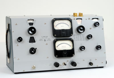 |
The HP 260A "Q" Meter
|
1969, The Boonton 260A
"Q" Meter, HP re-styled
In 1969, the original Boonton Radio 260A "Q" Meter was also re-styled to match the current HP instrument look, feel, and case color. Probably because it did not included any technical updates, the Boonton 260A was not renamed HP 260B.
Even more curiously, the HP 260A never appeared in any HP's general catalogs. In fact, this HP version of the Boonton 260A had a very short life because the HP 4342A, (see below) was in development, and was introduced by the end of 1970.
The main specifications of the HP 260A are exactly the same as those of the Boonton 260A: frequency range of 50 kHz to 50 MHz; continiously variable in 8 overlapping bands; and a range of "Q" measurement from 10 to 625.
HP 4328A, HP 4329A Measurement of Resistances, "High & Low"
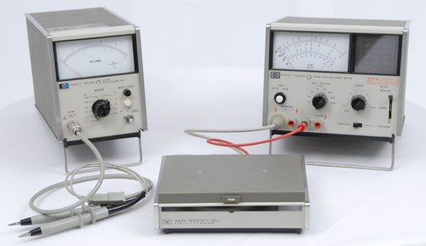
The HP 4328A Milliohmmeter was introduced in 1968, and the HP 4329A High Resistance Meter in 1969, they were both instruments for measuring resistances from very low to very high values. They were described in the March 1971 issue of the Hewlett Packard Journal, in an article entitled "Very High and Very Low Resistances - Why and How They are Measured." This happened at a time when properties of materials and quality of semi-conductor contact were a major concern. The ability to measure these extremes of the resistance range told a great deal.
The 4328A Milliohmmeter measures resistance from 1 Milliohm to 100 Ohms full scale in a 1, 3, 10 range selector sequence with a resolution of 20 µohms. Measurement is made by applying a 1000 Hz signal across the sample, where the maximum amplitude voltage is less than 20 mV peak in any case. The constant current signal is applied to the device under test through a 4-terminal Kelvin probe. Three different sets of Kelvin probes were delivered with the HP 4328A, to adapt to the various configurations which could be encountered when measuring very low resistances. During the design of these probes, very clever solutions were found by the YHP engineers for the tough cases, like the residual contact resistance measurement of connector for example. The 4328A with its original probe set, is still today an invaluable instrument in the electronic workshop. Faulty old electronic gear is frequently a question of bad contact. The 4328A and its handy probes have not yet got any competiton for tracing a dry solder joint or an oxidized contactor.
The 4329A Measurement area is Resistivity. Related to resistance, resistivity (p), is the characteristic of a material rather than of a particular specimen of that material. The resistivity of copper, for example, is 1.7 x 10E-6 ohm-cm, and that of quartz is about 10 E14 ohm-cm. Resistivity is of importance when considering the fundamental behavior of materials, as in solid-state physics. Surface and volume resistivities of solids such as printed circuit board materials, plastics, resins, refractories, semiconductor materials, oils, solvents and fabrics require high-resistance measurement capability. Other more common applications include measurements of capacitor insulation, and relay coil resistance. Accurate high-resistance measurements are needed to examine effects of temperature, humidity, and surface conditions on a variety of insulating devices and materials. The 4329A measures resistance in the range of 500,000 ohms to 2 x 10E16 ohms. The high resistance meter has automatic range and lighted multiplier indicator for an easy to read measured value. The accessory Model 16008A Resistivity Cell permits more convenient measurement of volume and surface resistivities of material samples.
 |
|
HP 4328A Milliohmmeter (left) and HP 4329A High Resistance Meter (right) - HP 16008A Resistivity Cell (center) |
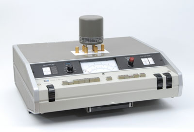 |
HP 4342A "Q" Meter
|
1970, Measuring Q, Easier and Faster. The HP 4342A Q meter
Since the mid-1930's, the Boonton Q Meter (later named HP Model 260A and shown above) has been an easy and common means of measuring Q. To make Q measurements even less complicated and make them over a wider range, the HP Model 4342A was designed by the Yokogawa-Hewlett-Packard R&D teams.
The HP Model 4342A was all solid state and covers a Q range of 5 to 1000 in a frequency band from 22 kHz to 70 MHz. Pushbutton controls and automatic leveling eliminate many dial adjustments and reduce measurement time. The fragile thermocouple element which was subject to accidental burnout in the Model 260A has been eliminated.
The HP 4342A has stayed until today one of the most precious instrument in the RF workshop for anyone having to deal with coils and their figure of merit. Using the 4342A is purely instinctive. Just having the instrument in your hand gives and immediate feeling of the complex phenomena which is electronic circuit resonance. Without question the Q Meter is also an instrument of great educative value. From time to time some units can still be found on the second hand market. The most beautiful ones are frequently sold between $400.00 to $800.00 USD. The quality of manufacture and the usefulness of the instrument largely justify such a price. The HP 4342A introduction price was $1500,00 USD in 1970.
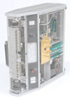
Animation Display: Interior Panoramic View of the HP 4342A
Animation |
 |
|
|
Use your scrollwheel to zoom in/out
--
Click and drag to view other parts of the image when zoomed |
|
|
|
Top-Inside View of the 4342A Q Meter
|
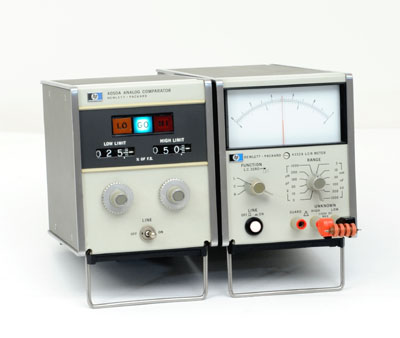 |
HP 4332A Analog LCR Meter with HP 4050A Analog Comparator
|
1972, HP 4332A
Another Yokogawa-Hewlett-Packard product, the HP 4332A LCR Meter was introduced in the 1972 general catalog.
The 4332A measures inductance, capacitance, and resistance with direct-readings linear meter scales. Measurement of L, C or R are made in 12 ranges. Inductances from 3 µH to 1000 mH full scale, Capacitances from 3 pF to 1000 nF full scale, and Resistances from 3 Ohms to 1 Megohm full scale.
The 4332A also provides a 1 Volt DC analog output at any full scale range. Combining the 4332A analog output with the 4050A Analog Comparator (also introduced in 1972) provides a rapid GO/NO-GO test system in sorting applications.
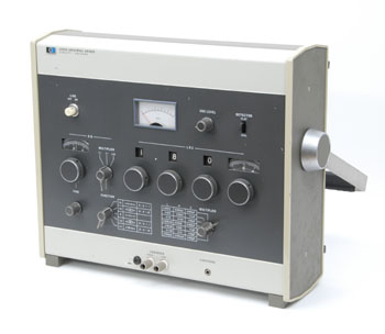 |
The HP 4265A Economical Universal Bridge
|
1973, HP 4265A Universal Bridge
The HP Model 4265A was introduced in the 1973 catalog. It is an Universal Bridge which provides an economical way to make high precision measurements of L, C, or R and D or Q.
Components can be measured in ranges of 0.1 µH to 1111 H in inductance, 0.1 pF to 1111 µF in capacitance and 0.1 milliohm to 1111 Megohms in resistance.
The measurement frequency is 1 kHz with an internal oscillator or it can vary from 50 Hz to 10 kHz with an external oscillator. L and C measurements are performed over a wide range of loss with either series or parallel equivalent circuits selected by a function switch.
Basic measurement accuracy is 0.2% of reading for L, C, and R.
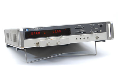 |
HP 4271A Digital LCR Meter
|
1973, HP 4271A
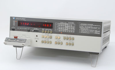
The first digital instrument dedicated to component tests and manufactured by HP was the 4270A Capacitance Bridge. It was fully automatic with a five-digit Nixie readout of capacitance from 18 pF to 1.2 µF and a .001 pF resolution.
One year later, the specifications of the first HP Digital LCR Meter were defined by the very fast evolution of the first generation of integrated circuits at this time. The 4271A was especially designed for the measurement of low-value components in integrated circuits and thin-film hybrid circuits, as well as of discrete components. The 4271A LCR Meter typically makes five or more readings per second to display capacitance from 0.001 picofarad to 19.000 nanofarads and inductance from 0.1 nanohenry to 1900.0 microhenry. The HP 4271A uses a four-pair measurement technique to reduce errors caused by stray capacitance, residual inductance, and mutual inductance of the test leads.
 |
HP 4262A Microprocessor based Digital LCR Meter
|
1978, HP 4262A LCR Meter
The HP 4262A is a 3 1/2 digit, microprocessor based digital LCR Meter. Introduced in the 1978 catalog, it had already been described in the December 1977 edition of the Hewlett Packard Journal.
The 4262A has fully automatic balancing, ranging and circuit mode selection. Test frequencies of 100 Hz, 1 kHz and 10 kHz can be selected. The microprocessor control allows other features such as automatic self test capability and deviation measurements.
The arrangement of the front panel keyboard switches insure maximum operating convenience and error-free operation. Individually LED lighted keys allow the user to easily determine the selected function at a glance. Several options are available for the user that needs systems capability. A BCD output of L, C, R, and D or Q data is available for use with a printer or calculator. If both data output and remote control are required, HP-IB compatibility is available.
Component Test, Fixtures and Accessories
The test fixture plays an important role in impedance measurement in both mechanically and electrically. The quality of the fixture determines the limit of the total measurement quality. HP supplied various types of test fixtures according to the type of component being tested. Many parameters have to be considered when testing components. Physical layout of the contacts is the most obvious one, but also the usable frequency range, residual parameters and the allowable DC voltage which can be applied are other important ones.
The picture below shows a variety of Hewlett Packard test fixtures of the 16000 Series. They are all of the four-terminals type, for use with balanced bridge LCR Meters. Still today, every HP and Agilent Technologies Balanced Bridge LCR Meters use a four BNC connector input terminal on which all the 16000 Series test fixtures can fit.
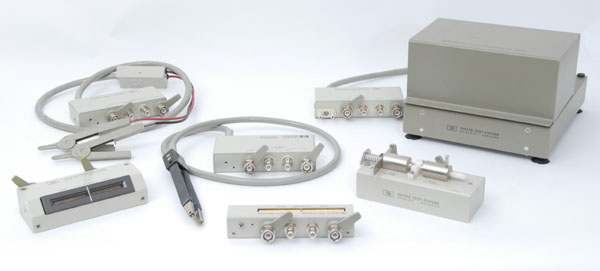 |
| Some 4-Wire Test Fixtures of the 16000 Series dedicated to component testing |
Just a little Japanese Wink
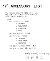
A copy of a 1977 test fixtures accessory and price list. The document lists every devices produced by the Yokogawa Hewlett Packard factory for the test of electronic components.
Most information is in Japanese, some is in English. Price are in Yens (1977 :-)
PDF File of Yokogawa Hewlett Packard Component Test Accessory listing
What Next ?
Up to the mid-seventies, most LCR Meters were of the balanced bridge type. The construction of balanced bridge was limited to the low frequency spectra in the range of 10 MHz. The other way to Characterize components in the VHF, UHF and Microwave frequency range was the network analysis. Vector volmeters and network analyzers had already existed since the early 60s, but deducting the absolute value of a component from the parameters measured with a network analyzer required a lot of calculation. Like for many other kind of measurements, Microprocessor would be the solution and the HP 4191A would be the first Impedance Meter of the Network Analyzer type in which a microprocessor computed the value of the tested component from the measured incident and reflected energy applied to it. This could be done for a complete set of frequencies, sweeping from 1 Megahertz up to 1 Gigahertz.
The next step looks so obvious today. Just wait for the microprocessor to improve its speed performance to make the calculations some thousand time each second, and you will have the ability to display the result on a CRT, real time ! This would be achieved during the next decade by the 4194 and 4195 Network Analyzer / Impedance Meter... They will be described in more detail in a chapter dedicated to the 1980-2000 period... In the near future, so... Stay tuned !
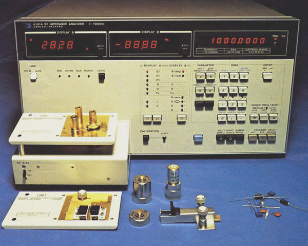 |
HP 4191A Impedance Analyzer - Cover of the January 1980 Hewlett Packard Journal
Courtesy of Hewlett-Packard Company |


