- Palo Alto Time -
Accuracy & Stability,
A major early concern.
Even if frequency standards were among the very early HP productions, we reserved the opening of a chapter dedicated to this category for the second part of the sixty year story because the sixties was the start of the real HP leadership in time frequency. The introduction of the world first transportable Cesium Beam Frequency Standard in 1964 marked the beginning of another long life HP's leadership.
Signal sources were the first HP production. They had a reputation for being stable and accurate. Measuring such characteristics needs a comparison to some other reference with better accuracy and stability than the source to be specified. That's the reason a frequency standard exists.
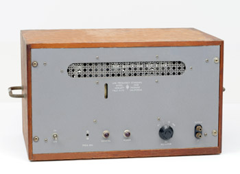 |
The HP 100B Frequency Standard
|
Early Frequency Standard
Crystal Controlled Secondary Frequency Standard
The very early production of a HP frequency standard was the HP 100A which is already listed in the 1943 catalog.
The next evolution was the HP 100B, introduced in the 1945 catalog, (Picture on the left) which put the 100 kHz Quartz Crystal reference into a temperature controlled oven. Then, the 100D in the 1950 catalog, added an internal oscilloscope for convenient frequency comparaison. The second edition of the Hewlett Packard Journal, October, 1949, was entirely dedicated to the Model 100D introduction and description.
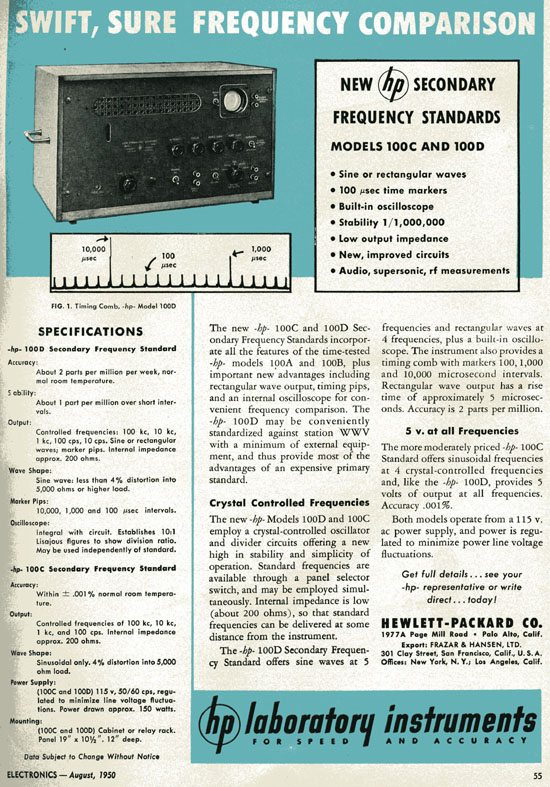
A lower cost version of the 100D, with slightly degraded performance, the HP 100C was also produced in 1950 as shown in the document below which is a copy of a full page ad. published by HP in the "ELECTRONICS" Magazine, August 1950.
| HP 100C & HP 100D advertisement in ELECTRONICS Magazine, August, 1950 - Page 55 |
 |
State of the Art Frequency Accuracy in 1960:
Most frequency standards build before 1960 used a 1 MC (Megahertz was called Megacycle in 1960) Quartz crystal enclosed in a temperature controlled oven.
The same time base was also used in HP frequency counters like the 524D (See "Early Electronic Frequency Counter" in the 1939-1960 period of the Quick Tour). The temperature controlled crystal oscillator was the state of the art in frequency stability and accuracy by the end of the 50s.
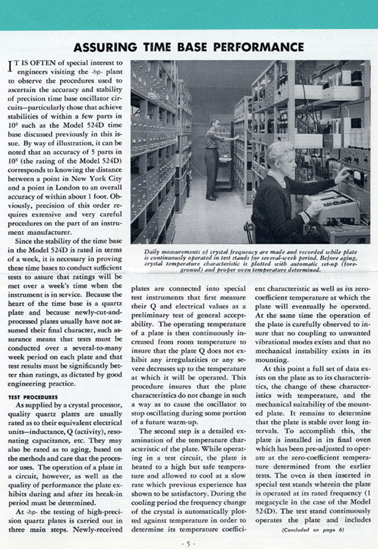
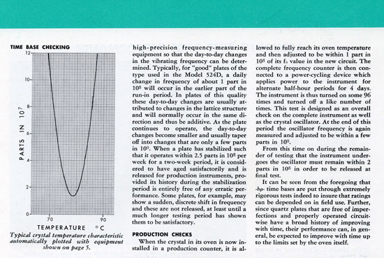
HP's achievement in time base performance is clearly illustrated by the article below. Published in the Hewlett Packard Journal volume 10, number 3-4. the article describes the long and complex process of quartz crystal adjustment and aging before it could be used in the high precision time base of HP instrument.
The Hewlett-Packard Application Note 200-2 is another fundamental reading about Quartz Crystals precision and stability when they are used as the controlling element of electronic oscillators. This document which is still today a reference, can be download in PDF format from here: "FUNDAMENTALS OF QUARTZ OSCILLATORS" (250 ko).
| Hewlett Packard Journal Nov-Dec 1958, page 5 - Copy by Permission of the Hewlett-Packard Company |
 |
| Hewlett Packard Journal Nov-Dec 1958, part of page 6 - Copy by Permission of the Hewlett-Packard Company |
 |
Bringing this Performance to the Bench
The contribution of HP to the electronic industry in the early '60s was to bring the performance described above within the reach of small companies having limited budget to invest in "in-house" frequency standards. Offering a wide choice of instruments to give the customer various solutions he could adapt to his needs was another concern.
Below are two examples of such secondary frequency standards available in the early 60s HP catalogs.
 |
The HP 100E Frequency Standard
|
The HP 100E in the 1961 Catalog:
5x10⁻⁸ Stability, Multiple Outputs for Test,
Production or Lab Use.
Good stability and the versatility of a wide variety of outputs are offered by the HP 100E Frequency Standard.
This compact instrument provides six standard sine and four pulse signals for use at many different stations on a production line or in the laboratory.
A particularly useful feature of the 100E is a timing comb providing output pips at 100, 1,000, and 10,000 µsec intervals to simplify sweep and time interval measurements.
The model 100E includes a built-in oscilloscope which may be used to calibrate external equipment such as oscillators through the use of Lissajous figures or to check the Standard's internal frequency division.
|
Use your scrollwheel to zoom in/out
--
Click and drag to view other parts of the image when zoomed |
|
|
|
Under Chassis Wiring of the HP 100E
|
 |
HP 103AR, Quartz Oscillator
|
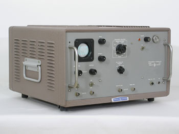
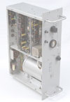
The HP 103AR
With the 103AR, introduced in the 1961 catalog, HP would reach the upper limit possible when using a 1 MHz Quartz crystal.
The crystal itself is one with a Q typically above 2.5 million and is aged in the circuit until its long-term drift is about 2 parts in 10E10 per day. Both the crystal and the oscillator circuit are housed in a double oven which is shock-mounted in the equipment. Even over a 0 to 50° C room temperature change, oven temperature is maintained within about 0.01° C.
Further enhancement of long-term stability were going to require the usage of higher frequency Quartz crystals. Five, then ten megahertz crystals were used and have become today's technology in the building of Quartz Secondary Frequency Standards.
Animation Display: Interior Panoramic View of the HP 103AR
Animation |
 |
|
Cesium Beam, the Big Leap Forward
Secondary Frequency Standards need better accuracy reference for their calibration.
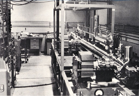
Calibration of a secondary frequency standard needs comparison to references with better accuracy. In 1963, such an accurate primary reference was only available in some national physical laboratories like the National Research Council in Canada or the Swiss Laboratory for Horological Research in Neuchâtel, Switzerland. These national time and frequency standards used the cesium-beam resonator technology. In the U.S.A., the "NBS III" was the third generation cesium-beam resonator built at the National Bureau of Standards. Its ascribed accuracy is +/- 6 parts in 10E12. The photo below shows this installation, the heart of which is the beam tube, a long cylinder on the right, which has an interaction lenght of 366 cm. The obvious limitation of these frequency standards was portability !
Hewlett Packard Journal August 1966, photo from page 17 - The NBS III Cesium-Beam Resonator in 1963
Copy by Permission of the Hewlett-Packard Company |
 |
 |
HP 5060A World First Transportable Cesium Beam Atomic Clock
HP Memory Project Collection |
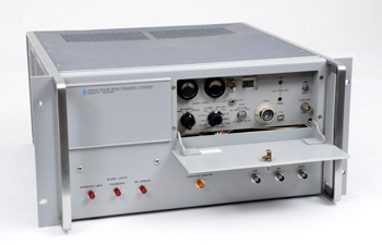
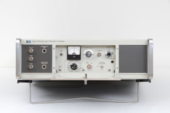
The HP 5060A,
The World's First Transportable
Cesium-Beam Atomic Clock
In 1964, HP technology alowed all the physical and electronical circuitry necessary to reproduce the functionalities of the NBS atomic clock to be enclosed into a single rack cabinet. This, with just a slightly lower specified accuracy of 2 parts in 10E11.
A very short-form description of the HP 5060A Clock theory of operation appears in the 1965 catalog:
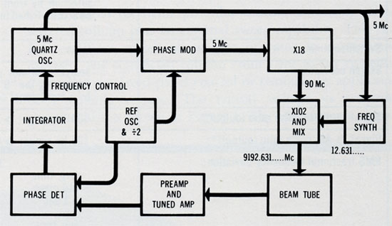
"In the atomic resonator of the 5060A a neutral beam of Cesium 133 atoms passes through a microwave cavity. When the frequency of the microwave magnetic field is near 9,192-631,770 cps (the hyperfine transition frequency of Cesium 133, defined in A-l time) it induces transitions from one hyperfine energy level to another. Those atoms which have undergone such a transition are then detected by a hot wire ionizer and electron multiplier. The microwave field, derived from a precision quartz oscillator by frequency multiplication and synthesis, is phase-modulated at a low audio rate. When the microwave frequency deviates from the center of atomic resonance the current from the electron multiplier contains a component alternating at the modulation rate and proportional to the frequency deviation. This component is then filtered, amplified and synchronously detected to provide a dc voltage proportional to the frequency deviation. The integral of this dc voltage is then used to automatically tune the quartz oscillator to zero frequency error."
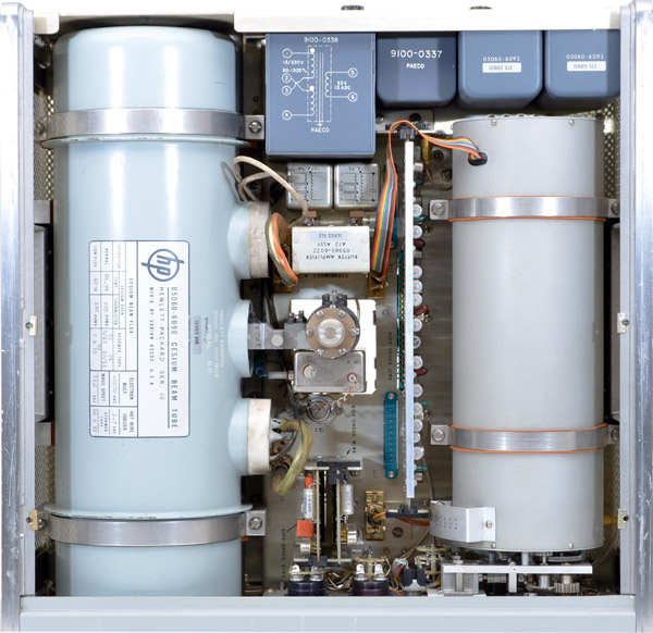
| Top-inside View of the HP 5060A Cesium-Beam Atomic Clock |
 |
Simplified Block Diagram of the HP 5060A Cesium-Beam Atomic Clock - 1965 Catalog, page 98
Courtesy of the Hewlett-Packard Company |
 |
Accessories for Improving the Accuracy of Frequency and Time Standards
In order to operate a frequency standard at or near its best attainable accuracy, it is necessary to minimize the error that may occur in comparing the local standard with the primary signal against which it will be calibrated.
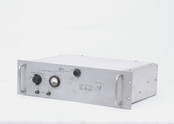
To simplify measuring and monitoring the performance of precision standard oscillator, and to increase the resolution with which intercomparison of local frequency standards and reference standards can be made, HP developed the Model 113BR, and 115BR Frequency Divider and Clock.
The HP 113AR, predecessor of the HP 113BR shown below, was introduced and described in the November-December 1959 edition of the Hewlett Packard Journal.
State of the art technology for frequency accuracy and timekeeping was sumarized in the Application Note Nbr. 52 edited in 1965. A scan of the original of this App. Note is available for download below.
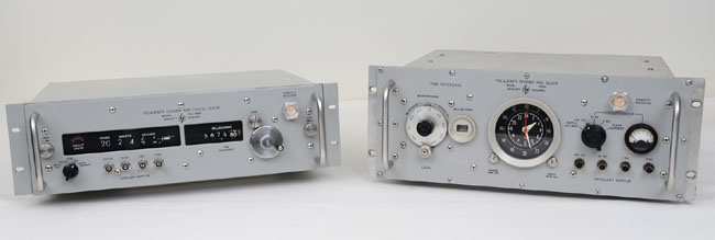
HP 115BR (left) and HP 113BR, Frequency Divider and Clock
|
 |
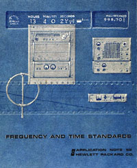
AN 52, 1965 Edition
FREQUENCY AND TIME STANDARDS
This Application Note explains the principles of precision frequency and time standards, with emphasis on practical working methods of frequency and time determination.
PDF File of the AN 52 (96 pages 24.5 Mb)
 |
Correlating Time from Europe to Asia With "Flying Clocks"
Photo Courtesy of the Hewlett-Packard Company
|
The Flying Clocks
In 1964, the highly accurate HP 5060A cesium-beam atomic clocks developed by Alan Bagley's Frequency and Time Division, were nicknamed "the flying clocks" when they were flown from Palo Alto to Switzerland to compare time as maintained by the U.S. Naval Observatory in Washington, D.C., to time at the Swiss Observatory in Neuchâtel.
Different campaigns were conducted from 1964 to 1966, transporting the "flying clocks" to many of the world's timekeeping centers from the U.S.A. to Europe and Asia which finally achieved a world-wide time synchronization. The three most important of these campaigns were accurately reported in the Hewlett Packard Journals: July 1964 - April 1965 and August 1966.
The scientific importance of this experiment was that even though the various national Cesium standards were based on atomic resonance, it was not possible to truly compare them to an adequate resolution, using radio connections. With technology demanding global time correlations for programs like the Apollo Moon shot, the Flying Clock performed beautifully in lowering the measurement uncertainty of international time.
In time, so to speak, the cesium-beam standard became the standard for international time.
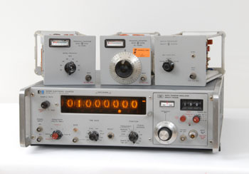
For fully portable operation, all the Necessary Hardware was Integrated
in a 19' Standard Rack Unit
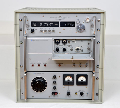
The picture below shows a panel view of a typical "atomic" clock configuration used in the Flying Clock experiment. The HP 5060A cesium standard in the middle drives HP 115BR electronic clock (top) which integrates standard frequency and also produces very accurate electrical "ticks" based on driving frequency. The Standby Power Supply unit at bottom provides for operation from a range of ac and dc voltages, and continued operation when AC line power is interrupted, such as when the Flying Clock rides in a passenger seat of an international airliner.
Reconstitution of a typical "atomic" clock configuration used in the Flying Clock experiment.
HP Memory Project Collection |
 |
More Information
More information, and all the documents dedicated to the Flying Clocks Experiment, published by Hewlett Packard from 1964 to 1977, are available on this website, Click HERE.
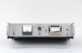 |
HP 117A VLF Comparator
|
Another Way, Lower Cost
Where and when available, another solution existed to benefit from the high accuracy of frequency standard without the cost of owning an in-house primary frequency standard. This solution consisted of receiving radio standard broadcast. Such transmissions of phase-stable low-frequency radio waves were made in the U.S.A. by the National Bureau of Standards on stations WWVB (60 kc) and WWVL (20 kc).
The HP 117A is a compact, complete solution to make accurate measurements of the phase difference between the 60 kc WWVB carrier and a stable local frequency. The phase difference measured in microseconds is automatically plotted on a built-in strip-chart recorder. The VLF comparator solution is obviously limited by conditions such as the geographic location or by the degree of accuracy required. But when it is possible, the cost is ten time less than the $12,000 cesium clock (1964 USD).
Seven, of the eight pages of the October 1964 Hewlett Packard Journal are dedicated to the HP 117A description.
 |
HP 5065A, Rubidium Vapor Frequency Standard
|
1969 - After Quartz & Cesium
a Third Technology: Rubidium
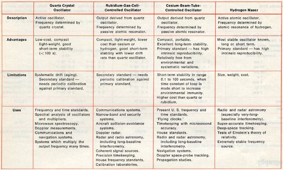
No single type of frequency standard is best for all applications. By the end of the 60s, two of the four types of precision frequency standards were already available in the HP's Time Frequency product line. One missing, the rubidium-gas-cell-controled oscillator technology was added in 1969 with the introduction of the HP 5065A, Rubidium Vapor Frequency Standard.
Even if being a secondary standard and needing periodic calibration against a primary standard, the rubidium technology has the advantage of being compact and light-weight. Its cost is lower than cesium or hydrogen maser and it is of very good short-term stability with lower drift rate than quartz oscillator.
The table below summarizes the advantages, limitations, and characteristics of Precision Frequency Sources available by the end of the 1960s. It was published in the Hewlett Packard Journal of July, 1968 and indicates some of their more frequent uses at this time.
Advantages, Limitations, and Uses of Precision Frequency Sources
Table from Hewlett Packard Journal July, 1968 - Courtesy of the Hewlett-Packard Company |
 |
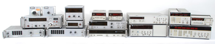
1960 - 1980 Frequency Counter Evolution
Just like many other measuring instruments, frequency counters were subjected to in-depth evolutions during this twenty year period. Picture below, shows some of the most significant frequency counters produced by HP from 1960 to 1979. Among the many available in the collection, we chose four of them which we consider to have contributed the most to the evolution of time and frequency measurements.
| 1960 <================================= 20 years of frequency counters evolution ==========================> 1979 |
 |
 |
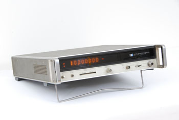
HP 5245M with various compatible drawers
|
1963 - in-line Readout
In 1963, a little over a decade after Hewlett Packard introduced Al Bagley's HP 524 first frequency counter, advances in the art had now permitted the development of a new generation of two high-speed frequency counters. The 5243L measures from 0 to 20 megacycles, and the 5245L from 0 to 50 mc. Both were transistorized and used a recent technology evolution for their display: NIXIE tube, in-line readout.
Except for their different maximum counting rates, the two counters have the same electrical and mechanical characteristics. Besides frequency, they can also measure period, time intervals, frequency ratios, and phase angles. The state-of-art, high stability quartz crystal oven, just described above, are used as the time bases of these counters, thus giving them a short term stability of +/- 5 parts in 10E10 (1 second averaging), and an aging rate of within +/- 3 parts in 10E9 per day.
A full array of plug-ins has been designed to be compatible with these "Mainframe" counters. Each of the plug-ins can be used with either of the counters. One of these, the 5253A of the frequency converter type, permits the counters to measure up to 512 mc.
 |
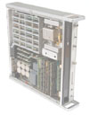
HP 5340A Microwave Frequency Counter
|
1972 - Microwave - Plug'n Read
Before the HP 5340A, measuring frequencies from low audio all the way to microwave had always required many different counters or counter plug-ins, a good deal of range switching and cable changing and at least -7 dBm (100 mV) of signal.
Not any more ! The 1972, new Model 5340A measured frequencies between 10 Hz and 18 GHz using only a single input connector. Measurements were completely automatic, and sensitivity was better than -25 dBm (12 mV) up to 18 GHz.
All these advances in a microwave counter, plus full HP-IB programmability, were obtained through the development of a set of new technologies. Model 5340A got its high sensitivity from new thin-film samplers used in is front end as harmonic mixers. A new phase locked-loop design provided automatic operation and reduced sensitivity to spurious input signals, harmonically related or not. Frequencies from 10 Hz to 250 MHz were counted directly, and frequencies above 250 MHz were measured using an automatic transfer oscillator technique.
Animation Display: Interior Panoramic View of the HP 5340A
Animation |
 |
|
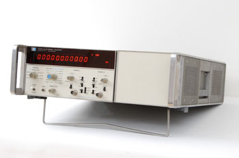 |
HP 5345A Universal Counter
|
1975 - "Reciprocal-Taking"
To make a frequency measurement, the 5345A first makes a period measurement, then inverts the period to get frequency, which it displays.
It is impossible to make a shorter description of the "Reciprocal Taking" counter technique. But, in short, the result of such a technique is a counter which can measure any frequency from 50 microhertz to 500 MHz, still maintaining a nine-digits resolution down to 1 Hz for a one-second measurement.
Even if the reciprocal counter technique seems simple, the quantity of components necessary to achieve the goal had to wait for the development of wideband digital logic circuits. The EEL and TTL logic circuit's fast evolution in the 1970s, coupled with HP labs custom high-speed logic circuits development, alowed this significant jump in the performance of general-purpose counters.
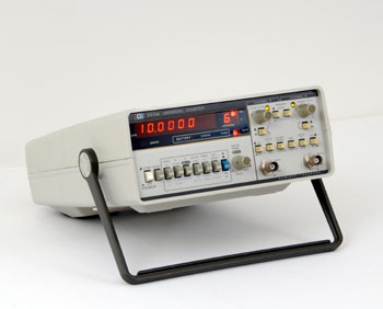 |
HP 5315A Portative Reciprocal Frequency Counter
|
1979 - The Reciprocal-Taking
Technique, Integrated
During the following four years, the first generation of microprocessors and Large Scale Integration (LSI) became powerful tools for the designer of measurement instruments.
In the HP 5315A/B Universal Counter, these two design tools were combined with an HP-made custom LSI chip containing all of the data-acquisition functions needed by a Universal Counter. The implementation of this IC was called a multiple-register counter (MRC) and found frequent usage in the next counter product line to come.
The 5315A/B resulted in a moderatly priced Universal Counter that accepted signals from DC to 100 MHZ on its both input channels. Its basic time interval resolution was 100 nanoseconds. The 5315A came in a rugged plastic case that was suitable for bench use and could be equipped with an optional internal battery pack for portable and field applications.
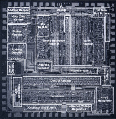
The Multiple Register Counter LSI developed for the HP 5315A/B Counters
Emitter Function Logic (EFL) circuits are used where high speed is needed
Integrated Injection Logic (I2L) is used for low power consumption and high density
From the HP Journal January, 1979 - Courtesy of the Hewlett-Packard Company |
 |