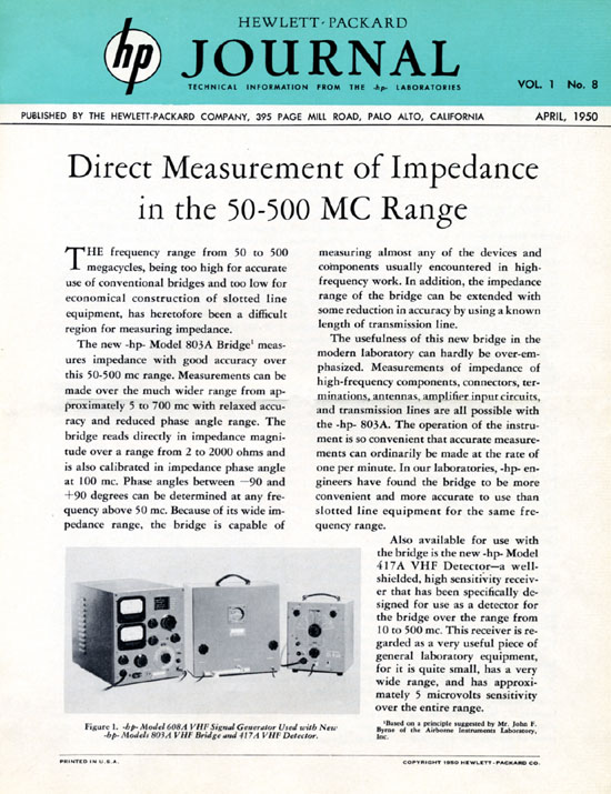
Direct Measurement of Impedance
In 1950 at about the same time as the introduction of the 805A microwave slotted line, a coaxial bridge operating in the VHF range provided for the first time a direct reading of the impedance magnitude and phase angle simultaneously.
 |
The HP 803A - VHF Bridge
|
The HP 803A VHF Bridge
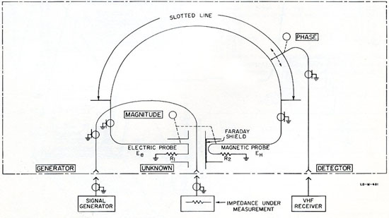
The Model 803A operates on the Byrne-bridge principle. Two probes are controlled simultaneously; one samples the E field while the other samples the H field. Each probe is connected through resistance to ground. The voltages developed across the resistors are applied to opposite ends of a slotted-line section. Impedance magnitude is determined by the positions the two probes have when they are adjusted so the voltages developed across their resistances are equal and therefore cancel each other at some point in the slotted line. Impedance phase angle is determined by the location of the cancellation point in the slotted line, as detected by a movable probe.
The Model 803A VHF Bridge, with an external rf signal source and a sensitive vhf receiver, can be used in the 55- to 500-mc range to measure impedance magnitude and phase angle. Impedance can be read directly in ohms; phase angle is indicated directly at 100 mc, and is easily computed at other frequencies. The impedance range is 2 to 2000 ohms.
Auxiliary Equipment Required:
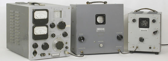
Operation of the Model 803A requires an external signal source and an external detector.
Signal Source: The rf signal generator must have amplitude modulation capabilities and an output of at least 1 milliwatt. HP VHF signal generators are suitable; the Model 608B can be used from 10 mc to 400 mc, and the Model 612A can be used from 450 mc to 500 mc.
Receiver: The detector used with the bridge should be a receiver preferably with a sensitivity at least 90 db below the level of the minimum input signal (1 mw). The HP Model 417A VHF Detector is designed to meet these requirements.
The RX Meter, a BOONTON RADIO Designed Instrument
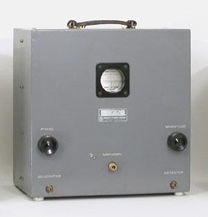
Another interesting instrument to be listed in this early network analyzer chapter is the 250 RX Meter. Two main reasons which make this instrument particularly significant are: On a technical point of view it is another early method to quantify the real and imaginary part of a component. On a business strategy point of view, the 250 RX Meter is not an original HP designed instrument. It is one of the first examples of the growing HP company strategy to buy other companies at the end of the 1950s. Hewlett Packard bought the Boonton Radio Corporation (BRC) in 1959. BRC was a well respected RF instrumentation company having a lot of well designed RF instruments in its catalog. The 250A RX Meter (the black one, on the left in picture below) was one of them. Obviously HP sold many of BRC's instruments, but even after they were fully absorbed, several instruments (202J, 202H, 207H, and 250A) lived on into the late 60's as HP models. (the 250B, HP restyled and upgraded in 1968, is the one pictured on the right below).
Before the "S" Parameters
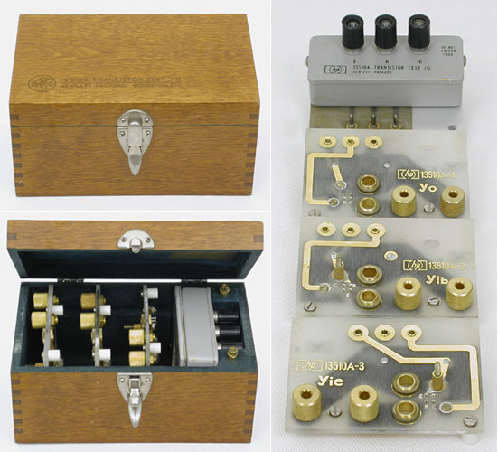
Ten years after the birth of the transistor, an interesting accessory to be used with the 250A RX Meter was introduced. One of the very first tools to characterize transistor parameters. The 13510A Transistor Test Jig is a set of fixtures which can be mounted on the 250A. A mounting adapter including bias filtering for an external power supply and three separate plug-in test circuit boards for measuring Yoe, Yib, and Yie.
- Yoe = Output admittance, common emitter configuration with input circuit shorted.
- Yib = Intput admittance, common base configuration with output circuit shorted.
- Yie = Intput admittance, common emitter configuration with output circuit shorted.
This solution would be satisfactory for the measurement of the transistors up to the end of the fifties. Performance and usable frequency range of transistors of this time was far below the 250 megahertz upper frequency limit of the RX meter. At frequencies above 100 MHz , Y parameters became increasingly difficult to measure because it was difficult to obtain good short, open circuits and because short circuits frequently caused the device to oscillate.
The increasing performance of the transistor in the beginning 1960s would lead the industry to use a slightly different set of parameters, the "S" or scattering parameters, which could easily be measured at frequencies above 100 MHz. Hewlett Packard would make the "S" parameters become the industry standard with the introduction of its 8405A, 1GHz, Vector Voltmeter in 1966.