 |
Outdoor Microwave Test
Courtesy of Hewlett Packard Company
|
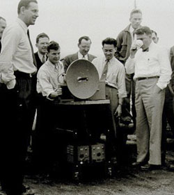
Microwave at HP
The photo on the left shows in the foreground, some of HP's Microwave celebrities of the 40s and 50s, from left to right:
W.Bruce Wholey Engineering Manager of the Microwave and Signal Generator Division. - E.F. Barnet Designer of a large part of the Waveguide Product Line. - Art Fong Designer of the 803A VHF impedance bridge and later in the early 60s, product manager of the Spectrum Analyzer Division. - Bill Hewlett is standing in the foreground on the right.
Most of the original Microwave team came from the MIT Radiation Laboratory created by the US government during World War II.
Microwave Generator,
A Fast Growing Product Line
The highly specialized team shown above would quickly add a full line of high frequency signal sources to the HP catalog. Starting in 1946, using the experience acquired for radar development during the war, Art Fong adapted the klystron tube technology for the production of the first HP microwave generator, the 616A was introduced in the 1948 catalog.
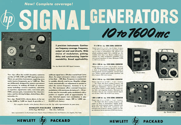
The product line grew quickly during the next two years to give HP the opportunity to announce complete coverage from 10 to 7600 megacycles in a two-page ad published in the November, 1950 ELECTRONICS magazine.
 |
| Dual Page Publicity in ELECTRONICS Magazine, November, 1950 |
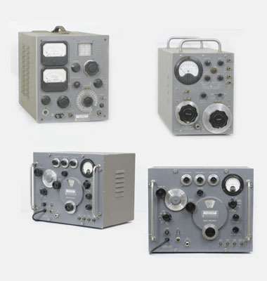 |
Right Page of the 1950 Publicity reconstructed with pieces of the collection:
Upper left HP 608A - Upper right HP 610B
Lower left HP 614A - Lower right HP 616A
|
10 to 7600 Mc Coverage
The November, 1950, Ads shown above argues that:
Now —hp— offers the world's broadest, easiest-to-use line of VHF, UHF and SHF signal generators. These are precision instruments supplying accurately known frequencies up to 7,600 mc. They are deliberately designed for utmost convenience and accuracy in making all kinds of measurements including: receiver sensitivity, selectivity or rejection; signal-noise ratio, conversion gain, SWR, antenna gain, transmission line characteristics ; and for driving bridges, slotted lines, filter networks, etc.
The listed instruments are:
- HP 618A - 3800 to 7200 mc
- HP 616A - 1800 to 4000 mc
- HP 614A - 800 to 2100 mc
- HP 610B - 450 to 1200 mc
- HP 608A - 10 to 500 mc
All these generators have variable output level from
0.1 µV to about 200 mV (1 milliwatt) into 50 Ohm.
 |
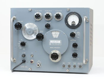
HP 624C SHF Test Set
|
SHF Test Sets
Also introduced during the fifties and built using the same techniques, a number of microwave test sets were designed for specific markets needs. Basically, these sets were signal generators with added circuitry for measuring external power levels and external frequency.
One of the sets, the model 624A, covers a range from 8500 to 10,000 mc. It is especially useful in testing radar transmitters and receivers, and includes a versatile pulser to facilitate such testing.
The model 623B has been designed for testing SHF relay stations such as are used in video and communications work. It can be obtained for any one of six frequency bands, each about 300 mc wide and overlapping from 5925 to 7725 mc.
These test sets can be consider as another "All tools in one box" approach, like was the 650A and 205AG in the audio spectrum.
.
High Precision Mechanical Design,
The accuracy, stability, and resetability of the microwave generator of this time, all depends mainly of the quality of their mechanical design.
In short, one could say that the quality of electronics of this era relies on the quality of mechanic. Hewlett Packard Journals of the 50s frequently describe innovative techniques and tools developed by the HP machining department to achieve the best performance of the final equipment.
Pictures below show the simplified diagram and mechanical design of the Klystron cavity oscillator, common to all the generators listed above except the 608A.
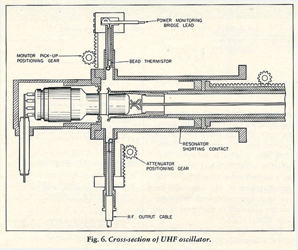 |
Cross-section of UHF klystron oscillator of the HP 616A Signal Generator - Hewlett-Packard Journal May-June 1952
Courtesy of the Hewlett Packard company |
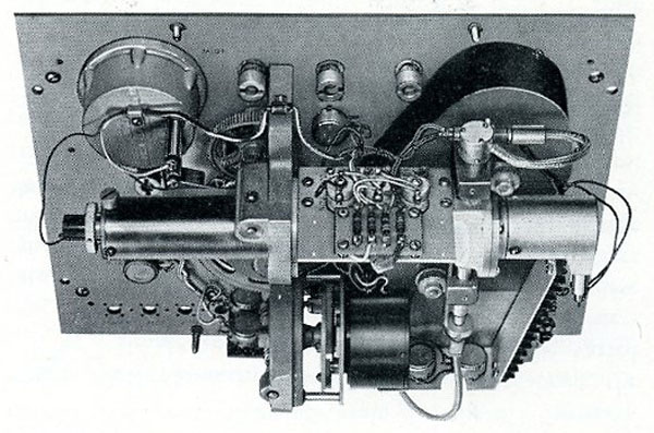 |
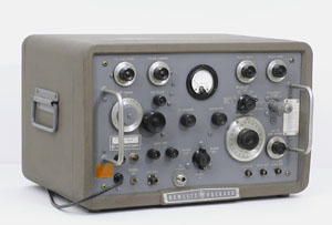
Rear view panel assembly of the HP 616A Signal Generator - Catalog 21-A 1952, page 63
Courtesy of the Hewlett Packard company |
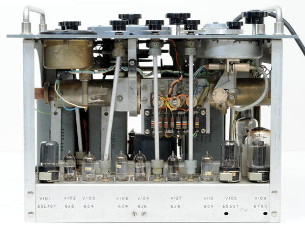 |
| Top Inside view of the HP 616A Signal Generator from the HP Memory Project Collection |
Another Kind of Microwave Signal Source,
the Swept Frequency Oscillator
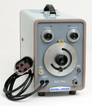 |
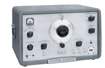
HP 670 SHF Swept Frequency Oscillator
|
HP 670 Series SHF
Swept Frequency Oscillators
The first of this new product line was the HP 670HM, introduced in the 1955 catalog page 76. It is a klystron, mechanically swept oscillator covering 7 to 10 Kmc and delivering 10 milliwatts output power over the full frequency range.
This 670 SHF Sweeper would give place quickly to a complete line of products of the same design with different frequency coverage. The 1957 catalog lists four different sweepers to cover the full spectra from 2.6 to 10 Kmc.
* HP 670SM - 2.6 to 4.0 Kmc
* HP 670GM - 4.0 to 6.0 Kmc
* HP 670JM - 5.8 to 8.2 Kmc
* HP 670HM - 7.0 to 10.0 Kmc
How it Works ? See diagram below
A motor drive is provided on each generator for automatic swept frequency operation over all or a portion of the frequency range. The swept frequency range is controlled by two adjustable stops located on the frequency dial. One stop locates the upper frequency limit; the other, the lower frequency limit. The minimum frequency range which can be swept varies from approximately 10% of the band for the lowest frequency unit (670SM) to approximately 20% of the band for the highest frequency unit (670HM). The sweep system operates at a constant velocity selected to provide an easily seen trace on a medium-persistence cathode-ray-tube. The velocity of the frequency dial is approximately 100 degrees of rotation per second.
In addition to driving the frequency dial, tuning plungers, the reflector tracking potentiometer, the motor also drives another potentiometer to obtain a sweep voltage for oscilloscopes which varies as the output frequency varies.
.
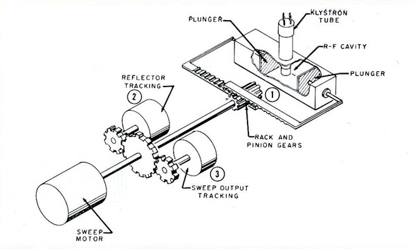 |
Operating Diagram of the HP 670 Series Swept Frequency Oscillator with Sweep Motor Drive
from Catalog 23-A 1957, page 93
Courtesy of the Hewlett Packard company |
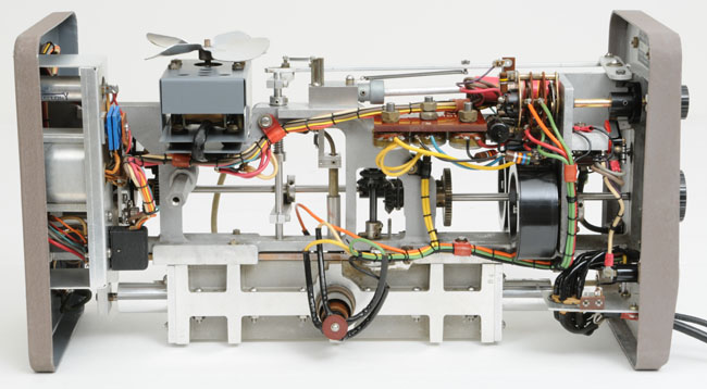 |
| Inside View (from the left) of a HP 670SM Swept Frequency Oscillator with Sweep Motor Drive |
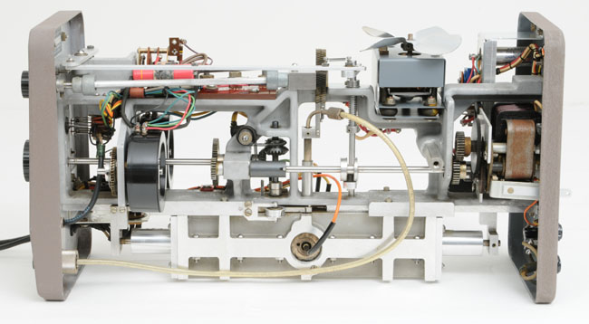 |
Inside View (from the right) of a HP 670SM Swept Frequency Oscillator with Sweep Motor Drive |
 |
HP 686A Electronic Sweep Oscillator
|
HP 686A,
First Electronic Sweep Oscillator
A new kind of Electronic Sweep Oscillator was introduced with the HP 686A in 1957, catalog 23-A, page 94. It uses a backward-wave oscillator that eliminates the sweep motors and tuning plungers of the previous generation, and thus their range limitations and mechanical problems.
Model 686A Sweep Oscillator generates CW and swept frequencies in the X band (8.2 to 12.4 KMC) at output levels up to 10 mw ( + 10 dbm) into a matched waveguide load.
The rf output frequency is swept linearly with time. A voltage-tuned backward-wave oscillator tube is employed as the rf signal source and is swept electronically through the desired frequency range, Delta FREQ. This total frequency change, Delta FREQ., is selectable in steps from 3 MC to 4.2 KMC. In addition a vernier is provided to adjust the deviation to values between steps. The rate at which the oscillator frequency is changed is variable in decade steps from 40 MC/sec to 400 KMC/sec.
The rf output frequency can be swept slowly enough for presentation on a recorder or fast enough for flickerless presentation on an oscilloscope. The rf sweep may be recurrent, triggered, or started manually for single sweep operation. A linear sweep voltage is provided which is concurrent with the rf sweep. This sweep voltage can be used for operating a recorder or an oscilloscope.
In addition to producing CW and swept frequency signals, the HP 686A may be amplitude and frequency modulated. A 400 to 1,200 cps square wave modulator is provided to amplitude modulate the 686A internally when used in conjunction with standing wave indicators, ratio meters or other tuned vacuum tube voltmeter devices.
.
A Complete Review of the First 20 Years Production of
Microwave Signal Sources and Measurement Accessories at HP
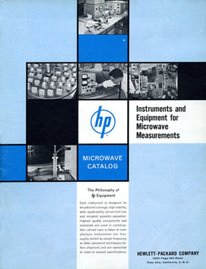 |
Cover of the 1961 Microwave Catalog
Courtesy of the Hewlett-Packard Company
|
Instruments and Equipment for
Microwave Measurements,
Dedicated Catalog
An exhaustive listing of the Microwave Product Line available at HP, by the end of the fifties, can be found in this 1961 MICROWAVE CATALOG. Its contents recap all the instruments and accessories available for the measurement of waveguide and coaxial systems by the beginning of the sixties.
Another useful characteristic of this catalog is the method of classification chosen which is that products are classified by their usable frequency range. A number of selection tables give an immediate overview of the various accessories available for each type of measurement, in each type of waveguide and inside its usable passband.
1961 Microwave Catalog ( PDF, 11.3 Mo )
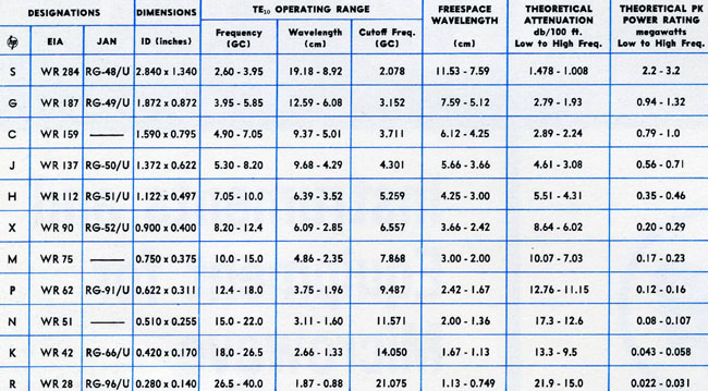
Chart of Standard Waveguide Specifications for Band S to Band R From the 1961 Microwave Catalog shown above
Courtesy of the Hewlett-Packard Company |
 |