Animation Display: Interior Panoramic View of the HP 211A


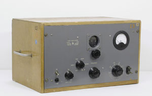 |
HP 650A - in its original wood box One of the oldest showpiece of the collection |
Modification of the original audio oscillators produced many signal sources with applications other than the audio frequency spectrum.
The 650A Test Oscillator was the first example which appeared in the 19-A, 1948 catalog. It covers from 10 cps to 10 Mc in six bands with a 15 milliwatts output level into 600 ohm, a +/- 1 dB flatness and better than 5 % distortion at 10 Megacycles.
It was the first HP instrument to bring audio frequency speed, accuracy and ease of operation to higher frequencies and to enable a wide variety of measurements in supersonic, video and RF bands. This would answer the needs of fast growing new industries like television wide band systems and telephone carrier measurements. The 650A can be considered as HP's first instrument in the telephone industry, a business which became an HP division some years later.
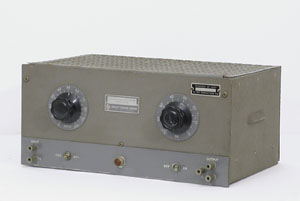 |
The HP 210A
|
The 210A was another signal source introduced in the 1943 catalog.
The 210A can be considered as the first HP pulse generator. Working from 20 cps to 100 Kc it can deliver up to 50 volts peak to peak with a 1 microsecond rise time for testing receivers, video amplifiers, networks and transmitters or to measure electronic circuitry time constant.
The 210A is not a self contained generator but rather a clipping amplifier which needs a sine wave input from an external generator.
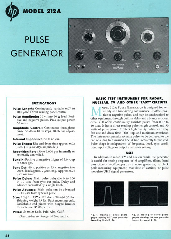
The first pulse generator to include the signal source was the 212A introduced in the 1950 catalog (20-A) on page 28 which is shown below.
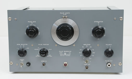 |
| The HP 212A |
| 212A Pulse Generator in the 1950 Catalog - Copy by permission of the Hewlett Packard Company |
 |
 |
The HP 200TR
|
Another variation in the HP 200 Series, the Model 200T was designed for high stability applications. Introduced in the 1955 short-form catalog, and described in the April 1957 issue of the Hewlett Packard Journal, the HP 200T was especially convenient for high-resolution work such as encountered in the telemetering field. Data telemetry was used extensively in real-time aircraft and missile testing of the time.
John Minck recalled the telemetry work his roommates were doing while he was in full scale bomb test at Eniwetok:
"A typical telemetry system was based on frequency multiplex technology. Consider a missile test where you wanted 10 channels of data, to use sensors to observe acceleration during flight, perhaps a gyro-system to record orientation, some temperature monitoring and some strain gauges to record stress. The telemetry transmitter might operate at a frequency of 1500 MHz. It would be modulated by a carrier of 1 kHz to 120 kHz. This band would be made up of subcarriers of say 5 kHz, spaced along that modulation band. The subcarrier amplifiers and filters necessary to combine the channels in the missile needed sharp skirts to prevent interfering with each other.
The carrier was FM modulated onto the transmitter signal, and the sub-carriers were FM modulated, leading to the terminology of FM-FM modulation. On the ground, those receivers needed separation filters and sharp skirt amplifiers to drive the strip chart recorders or often multichannel tape recorders. For design, production and operational testing, the test oscillator needed exceptional frequency stability to tune across those subcarrier elements. The 200T was the ideal stimulus signal."
The HP 200T worst case stability was specified at 20 Hz per hour at a 100 kHz operating frequency after warmup and, of course, was generally noticeably better in a typical case. As a result, the instrument was especially suited to high-selectivity work such as checking the response of narrow-band filters, and testing selective amplifiers.
The200T frequency range extends from 250 Hz to 100 kHz, with wide overlap at both end of each range. The five ranges cover:
The unusual color of this HP 200T in the HP Memory Project collection probably comes from a special order of the US Signal Corp. Recently obtained on EBay, the unit is labeled SG-118/MRQ-7. The rack-mount front panel has also an unusual thickness, about 5-times the thickness of a common series 200 instrument. Such thick and rigid front panels were often used for rack mounted instruments in mobile trailers to withstand rugged transport conditions. The left and right flanges of the cabinet are both in the HP standard paint color of that era. Another specific characteristic of this particular military ruggedized unit is that the bottom chassis wiring is tropicalized. See picture below.
 |
| The HP 200T Bottom view |
 |
| The HP 200T Top view |
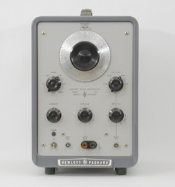 |
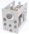
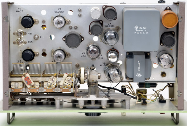
HP 211A
|
The last evolution in the 50s of the signal sources product line would be the 211A square wave generator introduced in the Hewlett-Packard Journal, May, 1955, volume 6, number 9.
Main specifications were: Continuous frequency coverage from 1 cps to 1 mc. Output 7 Volts across 75 ohms or 55 Volts peak-to-peak across 600 ohms with a rise time of 20 millimicroseconds (as noted in the specifications listing - Rise time value expressed in nanoseconds was not yet a current practice in 1954)